Table of Contents
Advertisement
Quick Links
Advertisement
Table of Contents

Related Manuals for INHENERGY SI 50K


Summary of Contents for INHENERGY SI 50K
- Page 1 User Manual SI 50K, SI 60K, SI 70K, SI 80K INHENERGY CO., LTD.
-
Page 2: Table Of Contents
CONTENTS 1 NOTES ON THIS MANUAL ....................... - 3 - 1.1 VALIDITY ..........................- 3 - 1.2 SYMBOLS IN THIS DOCUMENT ..................- 3 - 2 OVERVIEW ............................. - 4 - 2.1 PRODUCT INTRODUCTION ....................- 4 - 2.2 APPEARANCE ......................... - 5 - 3 INSTALLATION .......................... - Page 3 User Manual 8 DECOMMISSIONING ....................... - 16 - 8.1 REMOVE THE INVERTER ....................- 18 - 8.2 PACKAGING .......................... - 18 - 8.3 STORAGE AND TRANSPORTATION ................- 18 - 9 TECHNICAL DATA ........................- 18 - 10 MANUFACTURER WARRANTY ..................- 18 - 11 CONTACT ..........................
-
Page 4: Notes On This Manual
Additional information Find further information on special topics in the download area at www.inhenergy.com The manual and other documents must be stored in a convenient place and be available at all times. We assume no liability for any damage caused by failure to observe these instructions. -
Page 5: Overview
User Manual CAUTION indicates a hazardous situation which, if not avoided, could result in minor or moderate injury. NOTICE is used to address practices not related to personal injury Information that you must read and know to ensure optimal operation of the system. Markings on this product Symbol Explanation... -
Page 6: Appearance
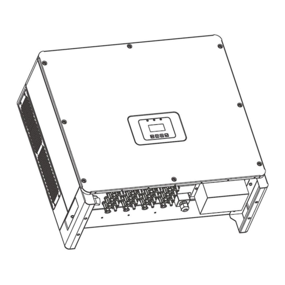
PV strings into AC power and feeds the power into the power grid. Models This document involves the following product models: SI 50K,SI 60,SI 70K,SI 80K; Model description (,SI 80K is used as an example) Model description Icon... -
Page 7: Installation
User Manual LED indicator description Category Status Meaning Blinking green at short intervals waiting status Blinking green at long intervals Self-check Steady green normal status Steady yellow Alarm No alarm Blinking red at short intervals Fault faultless Function button description Category Description ESC button: Return from current interface or function. -
Page 8: Mounting
Set screw( for mounting, external enclosure grounding) Cable gland for AC connection RS485 terminal (optional) Wifi module (optional) *C : SI 50K PV connectors (9*positive,9*negative); SI 60K /70K PV connectors (12*positive,12*negative); SI 80K PV connectors (16*positive,16*negative); *D: SI 50K PV pin connectors (5*positive,5*negative);... - Page 9 User Manual ◆ Not in direct sunlight. ◆ Not in areas where highly flammable materials are stored. ◆ Not in potential explosive areas. ◆ Not in the cool air directly. ◆ Not in environment of precipitation or humidity (>95%). ◆ Under good ventilation condition. ◆...
-
Page 10: Space Requirement
User Manual 3.4 Space Requirement 3.5 Mounting Steps 1.Use the wall bracket as a template to mark the position of the 5holes on the wall. 2.Drill holes with driller, make sure the holes are deep enough (at least 75mm) for installation, and then tighten the expansion tubes. -
Page 11: Electrical Connection
Table 3 Cable recommended Model Copper Cable Conductor crosssection Five-core cable SI 50K/SI 60K 2 AWG (L/N/PE) Five-core cable SI 70K/SI 80K 1 AWG (L/N/PE)... -
Page 12: Pv Connection
User Manual Connection Steps 1. Choose the appropriate wire(Cable size: refer to Table3). 2.Remove 10mm of insulation from the end of wire. 3.Insert stripped wires into AC terminal and ensure that all conductor strands are captured in the AC terminal.Compress the terminal head by using a crimping pliers . 4. - Page 13 User Manual SI 50K SI 60K SI 70K SI 80K ◆ Connecting the PV Array Danger to life due to lethal voltages! ◆ PV array supplies d.c voltage to inverter when exposed to light,before connecting the PV array, cover some light screens above PV arrays,ensure that the DC switch and AC breaker are disconnect from the inverter.
-
Page 14: 485 Connection
User Manual 4.3 485 Connection(Optional) ◆ 485 is provided the function of remote control that allows external control device to make the inverters remote cluster control through 485 port on the inverter. ◆ When routing the signal cable, ensure that it is separate from the power cable and away from interfering sources to prevent communication from being affected. -
Page 15: Turn-Off The Inverter
User Manual 4.4 Turn-off the Inverter Do not disconnect the DC connectors under load. Turn-off the inverter step: 1.Disconect the line circuit breaker from single-phases grid and prevent it from being reactivated. 2.Turn off the dc switch. 3.Check the inverter operating status. 4.Waiting until LED, OLED have go out, the inverter is shut down. - Page 16 User Manual - 15 -...
-
Page 17: Maintenance And Cleaning
User Manual 7 Maintenance and Cleaning 7.1 Maintain Periodically 1.Checking Heat Dissipation If the inverter regularly reduces its output power due to high temperature, please improve the heat dissipation condition. Maybe you need to clean the heat sink. 2. Cleaning the Inverter If the inverter is dirty, turn-off the AC breaker and DC switch ,waiting the inverter shut down ,then clean the enclosure lid, the display, and the LEDs using only a wet cloth. - Page 18 User Manual Check PV Check the PV PV Voltage ISO Low impedance to panel High ground configuration Please switch Check the PV DSP Comm. off DC switch. DC Curr High panel Error Restart the configuration invert Hw Invert High Invert I High Invert DCI High Contact the manufacturer...
-
Page 19: Decommissioning
Please be sure to deliver wasted inverters and packing materials to certain site, where can assist relevant department to dispose and recycle. 9 Technical Data Model SI 50K SI 60K SI 70K SI 80K Input Data Max. - Page 20 User Manual AC Output Data Rated output power 50KW 60KW 70KW 80KW Max. output power 55KW 66KW 77KW 88KW Rated output voltage 400V ±20% Rated output frequency 50 /60 Hz± 5 Hz Rated output current 101A 115A Max. output current 111A 128A Power factor...
-
Page 21: Manufacturer Warranty
2. Modules information 3. Communication method 4. Serial number of Inverters 5. Error code of Inverters 6. Display of inverter LCD INHENERGY CO., LTD. ADD: 6/F, Building No.4,No.1, Keji 7th Rd, Xiangzhou District, Zhuhai, Guangdong,China. P.C.: 519000 Tel: +86-756-368-9696 Web: www.inhenergy.com Email: info@inhenergy.com...
Need help?
Do you have a question about the SI 50K and is the answer not in the manual?
Questions and answers