Table of Contents
Advertisement
Quick Links
Advertisement
Table of Contents

Related Manuals for INHENERGY SI-33K-T2


Summary of Contents for INHENERGY SI-33K-T2
- Page 1 User Manual SI- 33/40K-T2,SI-45/60K-T2 INHENERGY CO., LTD...
-
Page 2: Table Of Contents
CONTENTS 1 NOTES ON THIS MANUAL ....................- 3 - 1.1 VALIDITY ........................- 3 - 1.2 SYMBOLS IN THIS DOCUMENT ................- 3 - 2 OVERVIEW ........................- 5 - 2.1 PRODUCT INTRODUCTION ..................- 5 - 2.2 APPEARANCE ......................- 5 - 3 INSTALLATION .........................- 7 - 3.1 CHECK FOR PHYSICAL DAMAGE ................ - Page 3 User Manual 8.1 REMOVE THE INVERTER ..................- 19 - 8.2 PACKAGING ......................- 19 - 8.3 STORAGE AND TRANSPORTATION ............... - 19 - 9 TECHNICAL DATA ......................- 19 - 10 MANUFACTURER WARRANTY ................... - 19 - 11 CONTACT ........................- 21 - - 2 -...
-
Page 4: Notes On This Manual
Additional information Find further information on special topics in the download area at www.inhenergy.com The manual and other documents must be stored in a convenient place and be available at all times. We assume no liability for any damage caused by failure to observe these instructions. - Page 5 User Manual NOTICE is used to address practices not related to personal injury Information that you must read and know to ensure optimal operation of the system. Markings on this product Symbol Explanation Caution,risk of electric shock Caution,hot surface Operation after 5 minutes Read the manual Point of connection for grounding protection CE mark.
-
Page 6: Overview
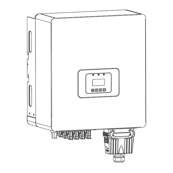
The Inverters is a three-phase grid-tied PV string inverter that converts the DC power generated by PV strings into AC power and feeds the power into the power grid. Models This document involves the following product models: SI-33K-T2,SI-36K-T2,SI-40K-T2; SI-45K-T2,SI-50K-T2,SI-60K-T2; Model description (,SI-60K-T2 is used as an example) Model description... - Page 7 User Manual ①⑪ LED indicator ② LCD display ③ Function button ④ DC switch ⑤ DC input terminals (PV1) ⑥ DC input terminals (PV2) ⑦ DC input terminals (PV3) ⑧ GPRS/WIFI output port ⑨ Communication port (RS485)t ⑩ AC output port ⑪Cooling fan LED indicator description Category Status...
-
Page 8: Installation
User Manual Function button description Category Description ESC button: Return from current interface or function. Down button: Move cursor to downside or decrease value Up button: Move cursor to upside or increase value. OK button: Confirm the selection. 3 Installation 3.1 Check for Physical Damage Make sure the inverter is intact during transportation. -
Page 9: Mounting
User Manual Object Description Quantity Inverter Bracket PV connectors (12*positive,12*negative) 12/12 PV pin connectors (12*positive, 12*negative) 12/12 User manual Expansion tubes Expansion screws Ring terminal Set screw( for mounting,external enclosure grounding) Wifi module (optional) RS485 connector (optional) *C : 33-36K PV connectors (6*positive,6*negative); 40K PV connectors (8*positive,8*negative);... - Page 10 User Manual 2.Inverter must be supported or strengthened if the wall’s strength isn’t enough(such as wooden wall, the wall covered by thick layer of decoration). Please avoide direct sunlight, rain exposure, snow laying up during. ◆ The slope of the wall should be within 15°. - 9 -...
-
Page 11: Space Requirement
User Manual 3.4 Space Requirement 3.5 Mounting Steps 1.Use the wall bracket as a template to mark the position of the4 holes on the wall. 2.Drill holes with driller, make sure the holes are deep enough (at least 60mm) for installation, and then tighten the expansion tubes. - Page 12 User Manual - 11 -...
-
Page 13: Electrical Connection
User Manual 4 Electrical Connection 4.1Grid Connection 33-60KW series inverter are designed for three-phase grid. Voltage is 400V, frequency is 50/60Hz. Other technical requests should comply with the requirement of the local public grid.Micro-breaker should be installed between inverter and grid, any load should not be connected with inverter directly. -
Page 14: Pv Connection
User Manual 4.2 PV connection ◆ Conditions for DC Connection The inverter has 3 independent input : PV1 & PV2& PV3 Notice that the connectors are in paired (male and female connectors). The connectors for PV arrays and inverters are H4 connectors;... -
Page 15: 485 Connection
User Manual Connection Steps: 1. Choose the 12 AWG wire to connect with the cold-pressed terminal. 2. Remove 7mm of insulation from the end of wire. 3. Insert the insulation into pin contact and use crimping plier to clamp it. 4. -
Page 16: Turn-Off The Inverter
User Manual 4.4 Turn-off the Inverter Do not disconnect the DC connectors under load. Turn-off the inverter step: 1.Disconect the line circuit breaker from single-phases grid and prevent it from being reactivated. 2.Turn off the dc switch. 3.Check the inverter operating status. 4.Waiting until LED, OLED have go out, the inverter is shut down. -
Page 17: Lcd Operation
User Manual 6 LCD Operation The main interface is the default interface, the inverter will automatically jump to this interface when the system started up successfully or not operated for a period of time. Menu interface - 16 -... -
Page 18: Maintenance And Cleaning
User Manual 7 Maintenance and Cleaning 7.1 Maintain Periodically 1.Checking Heat Dissipation If the inverter regularly reduces its output power due to high temperature, please improve the heat dissipation condition. Maybe you need to clean the heat sink. 2. Cleaning the Inverter If the inverter is dirty, turn-off the AC breaker and DC switch ,waiting the inverter shut down ,then clean the enclosure lid, the display, and the LEDs using only a wet cloth. - Page 19 User Manual Soft start erro Imbalance Check PV Check the PV PV Voltage ISO Low impedance to panel High ground configuration Please switch Check the PV panel DSP Comm. off DC switch. DC Curr High configuration Error Restart the invert Invert High Invert I High...
-
Page 20: Decommissioning
◆ When the inverter or other related components need to be disposed. Have it carried out according to local waste handling regulations. Please be sure to deliver wasted inverters and packing materials to certain site, where can assist relevant department to dispose and recycle. 9 Technical Data Model SI-33K-T2 SI-36K-T2 SI-40K-T2 SI-45K-T2 SI-50K-T2 SI-60K-T2 Input Data Max. - Page 21 User Manual MPPT max. current 45A*2 45A*2 52A*2 45A*3 45A*3 52A*3 AC Output Data Rated output power 33KW 36KW 40KW 45KW 50KW 60KW Max. output power 36KW 40KW 44KW 50KW 55KW 66KW 400V ±20% Rated output voltage 50 /60 Hz± 5 Hz Rated output frequency Rated output current Max.
- Page 22 2. Modules information 3. Communication method 4. Serial number of Inverters 5. Error code of Inverters 6. Display of inverter LCD INHENERGY CO., LTD. ADD: INHE Smart Power Distribution Industrial Base, Hi-tech Zone, Zhuhai, China. P.C.: 519000 Tel: +86-756-368-9696 Web: www.inhenergy.com Email: info@inhenergy.com...
Need help?
Do you have a question about the SI-33K-T2 and is the answer not in the manual?
Questions and answers