
Related Manuals for INHENERGY HI-3K-SL


Summary of Contents for INHENERGY HI-3K-SL
- Page 1 User Manual HI-3K-SL, HI-3.6K-SL, HI-4K-SL,HI-4.6K-SL, HI-5K-SL, HI-6K-SL V1.3 INHENERGY CO., LTD...
-
Page 2: Table Of Contents
CONTENTS 1 OVERVIEW .........................1 1.1 Product Introduction ....................1 1.2 Appearance........................2 2 NOTES ON THIS MANUAL ....................3 2.1 Validity .......................... 3 1.2 Symbols in this document ................... 3 3 INSTALLATION ........................4 3.1 Check for Physical Damage ..................4 3.2 Packing List ........................4 3.3 Mounting ........................ - Page 3 User Manual 2.3.2 Parameter setting ....................22 PARALLEL CONNECTION IN THREE PHASE SYSTEM ..........25 PARAMETER SETTING .................... 26 3.3.1 Check before setting....................26 3.3.2 Parallel setting ...................... 26 5 POWERING ON THE SYSTEM .................. - 30 - 5.1 Start-Up the inverter....................- 30 - 6 POWERING OFF THE SYSTEM .................
- Page 4 User Manual 11 APPENDIX ......................... - 48 - 12 MANUFACTURER’S WARRANTY ................- 49 - 14 CONTACT ........................- 49 - - 3 -...
-
Page 5: Overview
Models This document involves the following product models: HI-3K-SL, HI-3.6K-SL, HI-4K-SL, HI-4.6K-SL, HI-5K-SL, HI-6K-SL. Model description (HI-6K-SL is used as an example) (1 – Product – Hybrid Inverter; 2 – Power Level – 6K Rated Power 6kW; 3 – Topology –... -
Page 6: Appearance
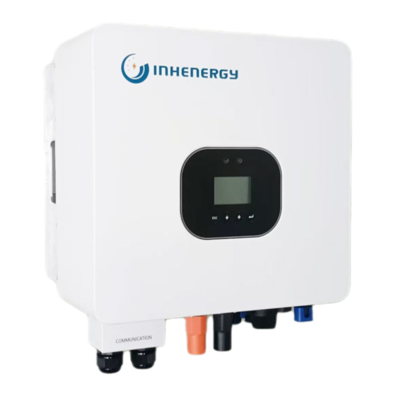
User Manual 1.2 Appearance ① LED indicator ② LCD display ③ Function button ④ Communication port ⑤ GPRS/WIFI output port ⑥ Battery Terminals (+) ⑦ Battery Terminals (-) ⑧DC switch ⑨ Grid Port ⑩ DC input terminals (PV1) ⑪DC input terminals (PV2) ⑫ GEN Port ⑬... -
Page 7: Notes On This Manual
The manual and other documents must be stored in a convenient place and be always available. We assume no liability for any damage caused by failure to observe these instructions. For changes in this manual, Inhenergy Co., Ltd. accepts no responsibilities to inform the users. 1.2 Symbols in this document Please pay close attention to all the symbols for the purpose of avoiding possible personal injury or equipment break down. -
Page 8: Installation
User Manual Symbol Explanation Caution,risk of electric shock Caution,hot surface Operation after 5 minutes Read the manual Point of connection for grounding protection CE mark. The inverter complies with the requirements of the applicable CE guidelines. The inverter must not be disposed of with the household waste. Warning, high voltage. - Page 9 User Manual * P: Object Description Quantity Inverter Bracket PV connectors (2*positive,2*negative) PV pin connectors (2*positive, 2*negative) User manual Expansion tubes Expansion screws Ring terminal Set screw (for mounting,external enclosure grounding) grid output connector Load/GEN connector Lead-acid battery temperature sensor Meter (optional) Wi-Fi module (optional) RJ45 connector...
-
Page 10: Mounting
User Manual 3.3 Mounting Installation Precaution HI-3/6K-SL series inverter is designed for outdoor installation (IP 65). ◆ Not in direct sunlight. Make sure the installation site meets the following conditions: ◆ Not in areas where highly flammable materials are stored. ◆... -
Page 11: Space Requirement
User Manual 3.4 Space Requirement 3.5 Mounting Steps 1.Use the wall bracket as a template to mark the position of the 3 holes on the wall(unit: mm). 2.Drill holes with driller, make sure the holes are deep enough (at least 60mm) for installation, and then tighten the expansion tubes. - Page 12 User Manual Page 8 of...
-
Page 13: Electrical Connection
User Manual 4 Electrical Connection ◆ For Australian safety country, the neutral cable of Grid side and Load side must be connected together, otherwise Load function will not work. System connection diagrams Page 9 of... -
Page 14: Pv Connection
User Manual ◆ Conditions for DC Connection 4.1 PV connection The inverter has 2 independent inputs: PV1 & PV2 Notice that the connectors are in paired (male and ◆ Connecting the PV Array female connectors). The connectors for PV arrays and inverters are H4 connectors. The solar modules connected to the inverter must conform to the Class A requirements of the IEC 61730 standard. -
Page 15: Battery Connection
User Manual ◆ Lead-Acid and other similar older-technology battery types require experienced and precise design, 4.2 Battery Connection installation, and maintenance to work effectively. For lead-acid battery bank, the inconformity between battery cells might lead to battery cell over-charge or discharge, and further might damage battery cells ◆... -
Page 16: Grid & Gen & Backup Connection
User Manual 4.3 Grid & GEN & Backup Connection An external AC switch is needed for grid connection to isolate from grid when necessary. ◆ Make sure inverter is totally isolated from any DC or AC power before connecting AC cable. Connection Steps 1. -
Page 17: Earth Connection
User Manual Load Connection & GEN Connection (Connection the same process) Diameter 10-14mm Area 6mm²or 10AWG Length 10mm 4.4 Earth Connection Users must additionally earth the inverter to the enclosure of a second earthing or equipotential bonding. This prevents electric shock if the original protective conductor fails. Earth Connection Steps: 1. -
Page 18: Communication Connection
User Manual 4.5 Communication Connection 1.Function port definition Object Category Description RS485/CAN/NTC port for battery communication DRMS For Australia market only Current transformer port1/ Meter communication port Reserve PARA1 Reserve PARA2 Reserve Upgrade firmware program port External devices communication port DIP Switch ◆... - Page 19 User Manual ◆ The CT in product box is compulsory for inverter system installation, used to detect grid voltage and 2.CT1 Connection current direction and magnitude, further, to instruct the operation condition of inverter via RS485 communication. ◆ Make sure inverter is totally isolated from any DC or AC power before ◆Direction of the CT cannot be connected in reverse, please follow “K→L”...
- Page 20 User Manual ◆ The meter is optional, used to detect grid voltage and current direction and magnitude, further to 2.Meter Connection (optional) instruct the operation condition of inverter via RS485 communication. Meter Connection Diagram: Description CT1-Pin Meter-Pin CT1_RS485B CT1_RS485A Page 16 of...
- Page 21 User Manual ◆ Using CAN or RS485 communication with lithium batteries. 4.BMS Connection ◆ Using lead-acid batteries, a temperature sensor must be connected. Connection Steps: ◆If you are using a lead-acid battery, you do not need to install CAN or ◆The CAN battery communication and RS485 battery communication RS485 communication.
-
Page 22: Contents
User Manual Inhenergy Single Phase Hybrid Inverter Parallel Guidance Manual Connection CONTENTS 1 SAFETY PRECAUTIONS ........................2 1.1 GENERAL SAFATY INSTRUCTIONS ..................2 1.2 PARALLEL SYSTEM SAFETY INSTRUCTIONS ............... 2 2 PARALLEL CONNECTION IN SINGLE PHASE SYSTEM ............4 2.11PH PARALLEL SYSTEM (PARALLEL BATTERIES, INVERTER QTY≤3 PCS ) ..... 4 2.21PH PARALLE SYSTEM (INDEPENDNT BATTERY, INVERTER QTY≤3 PCS) ....... -
Page 23: Safety Precautions
User Manual 1 Safety Precautions 1.1 General safety instructions Introduce the safety precautions that need to be followed during product installation and operation. ◆ Due to product version upgrades or other reasons, the content of the document will be updated from time to time. - Page 24 User Manual In the same system, the BACK-UP AC cable between the master and the slave, the ON-GRID AC cable between the master and the slave, and the DC cable between the battery and the inverter must ensure the conductor material, conductor cross-section, the area, conductor length, etc. are consistent. The monitoring module and smart meter are installed and connected to the master inverter.
-
Page 25: Parallel Connection In Single Phase System
User Manual 2 Parallel connection in single phase system 2.1 Parallel connection in single phase system (Batteries to be connected in parallel and inverter quantity should be less or equal to 3 pcs) 2.2 Parallel connection in single phase system (Battery to be connected as single unit and inverter quantity should be less or equal to 3 pcs) Page 21 of... -
Page 26: Parameter Setting
User Manual 2.3 Parameter setting 2.3.1 Check before setting To ensure a successful parallel connection, pls make sure below conditions are well met: Please refer to the user manuals of each equipment/device in the parallel connection network about installation and power on operation. Please make sure that all equipment/device in the parallel connection network, such as inverters, batteries, monitoring module and smart energy meter, are correctly installed and wired. - Page 27 User Manual 1. Communication port connection Please connect the parallel cables according to the following diagram. Ports "PARA1" and "PARA2" ◆ are used for parallel connection. For other port definitions, please refer to the inverter user manual. ◆ Page 23 of...
- Page 28 User Manual Please refer to the following diagram to make parallel cables. ◆ 2. Set master inverter. When multiple inverters are connected in single-phase parallel mode, make sure the parallel cables are connected correctly and powered on. All inverters will automatically change from stand-alone to slave and in standby mode.
-
Page 29: Parallel Connection In Three Phase System
User Manual 5. Set user function. When paralleling, you only need to set user functions on the master inverter. The system runs according to the parameters set on the master inverter. Most of the parameters set on the master will be automatically synchronized to the slave inverters. -
Page 30: Parameter Setting
User Manual 3.3 Parameter setting 3.3.1 Check before setting. To ensure a successful parallel connection, pls make sure below conditions are well met: 1 Please refer to the user manuals of each equipment/device in the parallel connection network about installation and power on operation. 2 Please make sure that all equipment/device in the parallel connection network, such as inverters, batteries, monitoring module and smart energy meter, are correctly installed and wired. - Page 31 User Manual 1 Communication port connection Please connect the parallel cables according to the following diagram. Ports "PARA1" and "PARA2" ◆ are used for parallel connection. other port definitions, please refer inverter user ◆ manual. Page 27 of...
- Page 32 User Manual Please refer to the following diagram to make parallel cables. ◆ 2 Set phase sequence. The inverter default set to phase A. When grouping three phase system, you need to set the other two phases to phase B and phase C that are consistent with the grid wiring. 3 Set master inverter.
- Page 33 User Manual 4 Set battery parallel. When multiple batteries are connected in parallel, that is, when battery side input on all inverters are connected in parallel, it is necessary to set the battery parallel enable on phase A master inverter, and the master battery communication cable should be connected to the BMS communication port of the phase A master inverter.
-
Page 34: Powering On The System
5 Powering On the System Before turning on the AC switch between the inverter and the power grid, use a multimeter set to the AC position to check that the AC voltage is within the specified range. 5.1 Start-Up the inverter 1.Turn on the DC switch between the battery and the inverter. - Page 35 User Manual Menu interface In normal, it will turn on page automatically, when pushing the button “UP”, the order of the paging information as follow: System Status System Status Battery Volt / Battery SOC System Time BAT:xx.xV/xxx% 20XX/XX/XX/XX:XX System Status Battery Power Serial Number Pbat: (+/-)XXXX W...
- Page 36 User Manual System Status System :ON/OFF System Status Charge Set System Status PeakLoadShifting System Status DisCharge Set System Status DisChargeLimit System Status SelfConsumption System Status Prevent BackFlow System Status Backup: Disable System Status System Status AC Volt: 230 V Back-up 240 V 208 V System Status...
-
Page 37: Enter Setting Interface
User Manual 7.1 Enter Setting Interface System Status System Status System Status System Status System Status “Enter ”5s System :ON/OFF SelfConsumption System Config Back-up PeakLoadShifting then release Press any key to light up the LCD, long press the "Enter" button for 5 seconds and then release it,user can enter to above setting interface, of which includes 5 types of setting contents. -
Page 38: Check And Set The Battery Type
User Manual 7.4 Check and Set the Battery Type System Status System Status BATx: XXX System Config Use the "↑" or "↓" and "Enter" buttons to enter the "System Config " in the battery type screen. User can check and set the corresponding battery type through this page. System Status BAT0: LeadAcid System Status... -
Page 39: Check And Set Ct2 Type (Optional)
User Manual 7.6 Check and Set CT2 Type (Optional) System Status System Status System Status CableCT / Meter System Config When an on-grid inverter is added to the energy storage system, a second CT/meter needs to be added so that the hybrid inverter can monitor the power generated by the on-grid inverter, thus, the load power and load power consumption can be measured correctly. -
Page 40: Inverter Used Under Peak Load Shifting Mode
User Manual Solar provides energy to loads as first priority, if Hybrid Ppv<Pload, battery energy and solar energy will Inverter Load supply to the loads at the same time. When PV is Off, battery energy will supply to the Hybrid loads. - Page 41 User Manual System Status Time1 System Status Time2 System Status System Status System Status Time3 Discharge Set PeakLoadShifting System Status Stop SOC: 100% System Status Power Rate: 100 % When the selling price of electricity is high or the battery needs to be discharged, user can press "↑"...
- Page 42 User Manual PeakLoadShifting Mode. When PV, Grid, Battery is available During charge time, solar energy will charge battery first. If Grid Hybrid Ppv>Pbat, extra solar energy will supply to the loads, and if Inverter Load Ppv>(Pbat+Pload), extra solar energy will feed in Grid. During charge time, solar energy will charge battery first.
-
Page 43: Inverter Used Under Self-Consumption Mode
User Manual 7.9 Inverter Used Under Self-consumption Mode When the system time of the inverter is not within the forced charging and discharging time set by "peak load shifting", or the forced charge/discharge time of "peak load shifting" is not enabled, the hybrid inverter automatically operates in self-consumption mode. The hybrid inverter detects the power of CT1/Meter1, when the PV is connected and the PV power is greater than the load power, the excess PV power will be output to the grid through CT1/Meter1. - Page 44 User Manual The hybrid inverter has an anti-backflow/0-export function. Users can use the "↑" or "↓" and "Enter" buttons to enter the "Prevent Back Flow" screen in "Self-Consumption" to set and enable the backflow prevention function. When the system has excess power to feed into the grid, the hybrid inverter limits the power output to the utility to the anti-backflow setting power (rated inverter power * backflow power percentage "Power Rate") via CT1/Meter1.
-
Page 45: Restore Default Factory Settings
User Manual 7.10 Restore Default Factory Settings System Status System Status System Status System Status Development Password:1111 Default Set System Config When user need to restore the system to factory settings, user can use the "↑" or "↓" and "Enter" buttons to enter the "System Config" interface and select the "Development" option. When enter to "Development"... - Page 46 User Manual Alarm ID Alarm Name Suggestion 1. Check whether the meter matches the inverter protocol. Meter COM Err 2. Check the wire connection between meter and inverter is good or not. 1.Check the lithium Battery is open or not. BMS COM Err 2.Check the connection of lithium Battery and inverter is good or not.
- Page 47 User Manual Alarm ID Alarm Name Suggestion Check the L line and N line is reversed or not. N-PE Fault! Check the PE s connected well or not. Check the connection of PV panels and inverter is good or not. PV Iso Low! Check the PE of inverter is good or not.
-
Page 48: Decommissioning
User Manual 9 Decommissioning ◆ Disconnect the inverter from DC Input and AC output. 9.1 Remove the Inverter ◆ Wait for 5 minutes for de-energizing. ◆ Disconnect communication and optional connection wirings. ◆ Remove the inverter from the bracket. ◆ Remove the bracket if necessary. ◆... -
Page 49: Technical Data
User Manual 10 Technical Data Model HI- 3K-SL HI-3.6K-SL HI- 4K-SL HI-4.6K-SL HI- 5K-SL HI- 6K-SL PV String Input data: Max. recommended PV power Max. DC voltage 550V Nominal voltage 360V Working 90V-550V voltage range Full load dc voltage 300V-450V range Start voltage/Minimum... - Page 50 User Manual Rated output 50 /60 ± 5 Hz frequency output 20A/22A current Max AC input current Power factor ±0.8 Maximum total <3% harmonic distortion Gird standard L+N+PE AC output Data (Back-up) : Peak output 4KVA , 4.6KVA , 5KVA , 5.6KVA ,...
- Page 51 User Manual Charging Strategy Self-adaption to BMS for Li-Ion Battery Charging Strategy 3 Stages for Lead-acid Battery Efficiency : MPPT efficiency 99.90% 99.90% 99.90% 99.90% 99.90% 99.90% Max. efficiency 98.00% 98.00% 98.00% 98.00% 98.00% 98.00% Euro weighted 97.50% 97.50% 97.50% 97.50% 97.50% 97.50%...
- Page 52 User Manual 11 Appendix Approved battery brands from Inhenergy. Brand RS485 or CAN JOHNRAY PYLON RS485 PYLON 3.0 RS485 DYNESS RS485 RS485 GenixGreen RS485 ZETARA RS485 RS485 Page - 48 -...
- Page 53 2. Modules information 3. Communication method 4. Serial number of Inverters 5. Error code of Inverters 6. Display of inverter LCD INHENERGY CO., LTD. ADD: INHE Smart Power Distribution Industrial Base, Hi-tech Zone, Zhuhai, China. P.C.: 519000 Tel: +86-756-368-9696 Web: www.inhenergy.com Email: info@inhenergy.com...
Need help?
Do you have a question about the HI-3K-SL and is the answer not in the manual?
Questions and answers