
Related Manuals for INHENERGY SI-4K-T2


Summary of Contents for INHENERGY SI-4K-T2
- Page 1 Solar Inverter Operation Manual Model: SI-4/6K-T2, SI-8/12K-T2, SI-13/20K-T2, SI -22/33K-T2 INHENERGY CO., LTD.
-
Page 2: Table Of Contents
CONTENTS 1 NOTES ON THIS MANUAL......................- 3 - 1.1 VALIDITY........................... - 3 - 1.2 SYMBOL DESCRIPTION......................- 3 - 2 OVERVIEW............................- 5 - 2.1 PRODUCT INTRODUCTION....................- 5 - 2.2 APPEARANCE..........................- 5 - 3 INSTALLATION..........................- 7 - 3.1 VISUAL CHECK........................- 7 - 3.2 PACKING LIST..........................- 7 - 3.3 MOUNTING.......................... - Page 3 8.1 REMOVE THE INVERTER....................- 19 - 8.2 PACKAGING........................... - 19 - 8.3 STORAGE AND TRANSPORTATION.................- 20 - 9 TECHNICAL PARAMETERS...................... - 20 - 10 MANUFACTURER'S WARRANTY..................- 20 - 11 CONTACT.............................- 24 - - 2 -...
-
Page 4: Notes On This Manual
The manual and other documents must be stored in a convenient place and be available at all times. We assume no liability for any damage caused by failure to observe these instructions. For possible changes in this manual, Inhenergy Co., Ltd. accepts no responsibilities to inform the users. - Page 5 NOTICE is used to address practices not related to personal injury Information refers tow what the operator must read and understand to ensure optimal operation of the system. Markings on this product Symbol Description Caution,risk of electric shock Caution,hot surface Operate after 5 minutes Read the manual Point of connection for grounding protection...
-
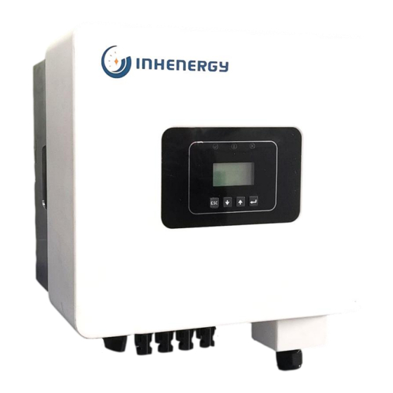
Page 6: Overview
The Inverter is a three-phase grid-tied PV string inverter that converts the DC power generated by PV strings into AC power and feeds into the power grid. Models This document is applicable for the following models: SI-4K-T2, SI-4K-T2, SI-6K-T2; SI-8K-T2, SI-10K-T2, SI-12K-T2; SI-13K-T2, SI-15K-T2, SI-17K-T2, SI-20K-T2; SI-22K-T2, SI-25K-T2, SI-27K-T2, SI-30K-T2;... - Page 7 ① LED indicator ② LCD display ③ Function button ④ DC switch ⑤ DC input terminals (PV1) ⑥ DC input terminals (PV2) ⑦ GPRS/WIFI output port ⑧ Communication port (RS485) ⑨ AC output port ⑩ Cooling fan LED indicator description Category Status Meaning...
-
Page 8: Installation
Function button description Category Description ESC button: Return from current interface or function. Down button: Move cursor to downside or decrease value Up button: Move cursor to upside or increase value. OK button: Confirm the selection. 3 Installation 3.1 Visual Check Make sure the inverter is intact during transportation. -
Page 9: Mounting
Object Description Quantity Solar Inverter Bracket PV connectors (4*positive,4*negative) PV pin connectors (4*positive, 4*negative) User manual Expansion tubes Expansion screws Ring terminal Set screw( for mounting,external enclosure grounding) Wifi module (optional) RS485 connector (optional) *C : 4-12K PV connectors (2*positive,2*negative); 13-17K PV connectors (3*positive,3*negative);... -
Page 10: Space Requirement
2.Inverter must be supported or strengthened if the wall’s strength isn’t enough(such as wooden wall, the wall covered by thick layer of decoration). Please avoid direct sunlight, rain exposure, snow laying up during winter. ◆ The slope of the wall should be within 15°. 3.4 Space Requirement - 9 -... -
Page 11: Mounting Steps
3.5 Mounting Steps 1.Use the wall bracket as a template to mark the position of 3 holes on the wall. 2.Drill holes with driller, make sure the holes are deep enough (at least 60mm) for installation, and then tighten the expansion tubes. 3. -
Page 12: Electrical Connection
4 Electrical Connection 4.1Grid Connection 4-30KW series inverters are designed for three-phase grid. Voltage is 400V, frequency is 50/60Hz. Other technical requests should comply with the requirement of the local public grid. Micro-breaker should be installed between inverter and grid, any load should not be connected with inverter directly. - Page 13 Table 3: Cable recommended Model Copper Cable Conductor cross-section 4mm² 4K-12K 6mm² 13K-17K Five-core cable(L/N/PE) 10mm² 20K-22K 16mm² 25K-30K Connection Steps 1. Choose the appropriate wire(Cable size:please refer to Table3). 2. Remove 12mm of insulation from the end of wire. 3.
-
Page 14: Pv Connection
13W-30KW: 4.2 PV connection ◆ Conditions for DC Connection The inverter has 2 independent input : PV1 & PV2 Notice that the connectors are in paired (male and female connectors). The connectors for PV arrays and inverters are H4 connectors; The solar modules connected to the inverter must conform to the Class A requirements of the IEC 61730 standard. - Page 15 ◆ Connecting the PV Array Danger to life due to lethal voltages! ◆ PV array supplies d.c voltage to inverter when exposed to light,before connecting the PV array, cover some light screens above PV arrays,ensure that the DC switch and AC breaker are disconnect from the inverter.
-
Page 16: Rs 485 Cable Connection
4.3 RS 485 Cable Connection(Optional) ◆ 485 is provided the function of remote control that allows external control device to make the inverters remote cluster control through 485 port on the inverter. ◆ When routing the signal cable, ensure that it is separate from the power cable and away from interfering sources to prevent communication from being affected. -
Page 17: Turn-Off The Inverter
4.4 Turn-off the Inverter Do not disconnect the DC connectors under load. Turn-off the inverter step: 1.Disconnect the line circuit breaker from single-phases grid and prevent it from being reactivated. 2.Turn off the dc switch. 3.Check the inverter operating status. 4.Waiting until LED, OLED have go out, the inverter is shut down. -
Page 18: Maintenance And Cleaning
7 Maintenance and Cleaning 7.1 Maintain Periodically 1.Checking Heat Dissipation If the inverter regularly reduces its output power due to high temperature, please improve the heat dissipation condition. Maybe you need to clean the heat sink. - 17 -... -
Page 19: Trouble Shooting
2. Cleaning the Inverter If the inverter is dirty, turn-off the AC breaker and DC switch ,waiting the inverter shut down ,then clean the enclosure lid, the display, and the LEDs using only a wet cloth. Do not use any cleaning agents (e.g. solvents or abrasives) 3. -
Page 20: Decommissioning
Invert I High Invert High Env T High Radiator Heat AC Contactor Voltage Check the PV panel configuration Alar Alarm ID Alarm Name Suggestion Alarm Name Suggestion m ID Replace the Clock Warn Fan 1 Speed Low internal button pool Normal shutdown at Active 0 Warn Fan2 Speed Low... -
Page 21: Storage And Transportation
◆ When the inverter or other related components need to be disposed. Have it carried out according to local waste handling regulations. Please be sure to deliver wasted inverters and packing materials to certain site, where can assist relevant department to dispose and recycle. 9 Technical Parameters Model SI-4K-T2 SI-5K-T2 SI-6K-T2 SI-8K-T2 SI-10K-T2 SI-12K-T2 Input Data Max. - Page 22 Grid system pattern 3W+N+PE Efficiency Max. efficiency 98.8% Europe efficiency General Data Dimensions(W/L/H)in 403/360/192 Weight <14kg <15kg Operation temperature –25 °C ... +60 °C range Noise ≤30dB Heat dissipation mode Natural IP Class IP65 Features LCD display Communication WiFi/GPRS/RS485 interface Model SI-13K-T2 SI-15K-T2...
- Page 23 AC Output Data Rated output power 13KW 15KW 17KW 20KW Max. output power 14.3KW 16.5KW 18.7KW 22KW Rated output voltage 400V ±20% Rated output frequency 50 /60 Hz± 5 Hz Rated output current Max. output current Power factor +-0.8 THDi <3% Grid system pattern 3W+N+PE...
- Page 24 Model SI-22K-T2 SI-25K-T2 SI-27K-T2 SI-30K-T2 Input Data Max. DC input power 28.6KW 32.5KW 28.6KW 32.5KW Max. DC input voltage 1100V Operation voltage range 250V-1000V Number of independent 2/2+2 2/2+2 2/3+2 2/3+2 MPPT/strings per MPPT MPPT max. current 28A/28A 28A/28A 42A/28A 42A/28A AC Output Data Rated output power...
-
Page 25: Manufacturer's Warranty
2. Module information 3. Communication method 4. Serial number of Inverters 5. Error code of Inverters 6. Display of inverter LCD INHENERGY CO., LTD. ADD: 6/F, Building No.4,No.1, Keji 7th Rd, Xiangzhou District, Zhuhai, Guangdong,China. Tel: +86-756-368-9696; Web: www.inhenergy.com Email: info@inhenergy.com...
Need help?
Do you have a question about the SI-4K-T2 and is the answer not in the manual?
Questions and answers