
Related Manuals for LUDLUM 2241-3RK


Summary of Contents for LUDLUM 2241-3RK
- Page 1 LUDLUM MODEL 2241-3RK RESPONSE KIT October 2017 Serial Number 238342 and Succeeding Serial Numbers...
- Page 2 LUDLUM MODEL 2241-3RK RESPONSE KIT October 2017 Serial Number 238342 and Succeeding Serial Numbers STATEMENT OF WARRANTY...
- Page 3 RETURN OF GOODS TO MANUFACTURER If equipment needs to be returned to Ludlum Measurements, Inc. for repair or calibration, please send to the address below. All shipments should include documentation containing return shipping address, customer name, telephone number, description of service requested, and all other necessary information.
-
Page 5: Table Of Contents
Main Board Controls Switch Board Controls Safety & Maintenance Considerations Environmental Conditions for Normal Use Detector Connector Warning Markings and Symbols Maintenance Operational Check Recalibration Batteries Detector Model 44-9 Tube Replacement Procedure Radiation Basics Radiation and Life Ludlum Measurements, Inc. October 2017... - Page 6 Model 2241-3RK Technical Manual The Unstable Atom Radioactive Decay Ionizing Radiation Measuring Ionizing Radiation What are the Health Risks from Ionizing Radiation? How Much Ionizing Radiation is Dangerous? Background Radiation 6-10 Manmade Radiation 6-11 Protection from Radiation 6-11 Standards and Regulation...
- Page 7 Model 2241-3RK Technical Manual Chassis Wiring Diagram, Drawing 408 × 101 10-5 Model 44-9 Alpha-Beta-Gamma Detector (Pancake) 10-6 Model 44-2 Gamma Scintillator 10-7 Model 133-7 G-M Detector 10-7 Drawings RS-232 Outputs Binary Output Format (15 Bytes) ASCII Output Format Ludlum Measurements, Inc.
-
Page 8: Introduction
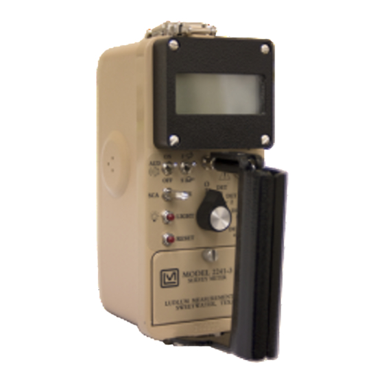
Section 1 Section Introduction he Model 2241-3RK is a first-responder kit that includes a portable microprocessor-based digital Scaler/ Ratemeter, as well as scintillation and Geiger-Mueller (GM) type detectors designed for the rugged use of first responders in the measuring of ionizing radiation. -
Page 9: The Detectors
Model 2241-3RK Technical Manual Section 1 Other features include: 1) Dead Time Correction (DTC) to compensate for detector dead time, 2) audible click-per-event with programmable 1, 10, 100, and 1000 divide-by; 3) LCD backlight with programmable time, 4) programmable fixed or variable response time, and 5) count overflow visual alarm, indicating that the counting circuitry is nearing the maximum counting capability. - Page 10 Model 2241-3RK Technical Manual Section 1 The Response Kit’s sodium iodide (Nal) gamma scintillator, Model 44-2, is used for the detection of low-level gamma radiation, in the range of 60 keV– 1.25 MeV. The detector is energy dependent, over-responding by a factor of 10 or greater in the 100 keV range, and under- responding by a factor of 0.5 above 1 MeV when normalized to...
-
Page 11: Getting Started
The Model 2241-3 serial number is located on the front panel below the battery compartment. Most Ludlum Measurements, Inc. detectors have a label on the base or body of the detector for model and serial number identification. -
Page 12: Operational Check
Model 2241-3RK Technical Manual Section 2 clockwise. Install two ˝D˝ size batteries in the compartment. Note the (+) and (–) marks inside the battery door. Match the battery polarity to these marks. Close the battery box lid. Note: The center post of a “D” size battery is positive. - Page 13 10. Check for a proper background reading: If using a Ludlum Model 44-9 detector, a typical reading would be 25-50 cpm or 8-15 uR/hr. If using a Ludlum Model 44-2 detector, a typical reading would be 1.4-2.6 kcpm or 8-15 uR/hr.
-
Page 14: Survey Techniques
AUD ON RATE instrument. Survey Techniques : When using the Ludlum Model 2241-3 Response Kit, the pancake Alpha detector (Model 44-9) must be used for detection of alpha. Keep in mind that moisture or dirt may block alpha particles, making them impossible to be measured. - Page 15 Model 2241-3RK Technical Manual Section 2 : To detect beta, the pancake detector (Model 44-9) must be used. Beta Move the detector over the area to be measured as slowly as possible (the instrument response time varies from 2 to 50 seconds).
-
Page 16: Specifications
Model 2241-3RK Technical Manual Section 3 Section Specifications : Readings are within 10% of true value with a detector connected. Linearity Instrument : Unit may be used immediately after the LCD initialization Warm-up Time sequence is completed (approximately 5 seconds after power-up). - Page 17 Model 2241-3RK Technical Manual Section 3 : display backlight activated by pushbutton LIGHT : built-in audio speaker (unimorph) with switch; at Audio AUD ON maximum volume > 60 dB at 0.61 m (2 ft); internal adjustable volume Alert/Alarm : indicated by either an...
-
Page 18: Model
Model 2241-3RK Technical Manual Section 3 : can display in R/hr, Sv/h, cpm, or cps Display Units : can display in seconds or minutes Time Base Audio Divide : 1, 10, 100, or 1000 events per click : variable or fixed ratemeter response (All stated times Response Time correspond to a range of 10% to 90% of the final reading). - Page 19 Model 2241-3RK Technical Manual Section 3 : low level gamma detection Indicated Use Model 44-2 Detector : 2.5 cm diameter x 2.5 cm thick (1 x 1 in.); sodium iodide (NaI) Scintillator T1 scintillator. : typically 175 cpm per µR/hr ( Sensitivity : 2.9 cm (1.1 in.) diameter;...
-
Page 20: Identification Of Controls And Functions
Model 2241-3RK Technical Manual Section 4 Section Identification of Controls and Functions Display The Model 2241-3 utilizes a four-digit liquid crystal display (LCD) with a two-digit overflow ( mode) and moving decimal point. SCALER The two smaller digits located in the lower right corner of the... -
Page 21: Front Panel Controls
Model 2241-3RK Technical Manual Section 4 mode when the six-digit display (four digits display and two overflow digits in right corner) reaches ˝999999˝ and starts to roll over again. : indicates that the batteries have decreased to the Low battery icon minimum operating voltage of 2.2 ±0.1 Vdc. -
Page 22: Front Panel Calibration Controls
(Discriminator): A multi-turn potentiometer (approximately 20 DISC revolutions) is used to vary the detector pulse-counting threshold from 2 to 100 millivolts. A Ludlum Model 500 Pulser or equivalent should be used in checking or adjusting the pulse discrimination parameter. Ludlum Measurements, Inc. -
Page 23: Main Board Controls
Note: When making adjustments to the potentiometers, make note of the following precautions: Use a Ludlum Model 500 pulser or high-impedance voltmeter with a high-voltage probe to measure the high voltage at the detector connector. If a Ludlum Model 500 Pulser is not available, ensure that the impedance of voltmeter used is 1000 megohms or greater. -
Page 24: Switch Board Controls
Model 2241-3RK Technical Manual Section 4 Switch Board Controls The switch board utilizes a 16-position rotary switch ( ) to FUNCTION select the 16 setup parameters. (Refer to schematics and component layout drawing near the end of the manual.) All of the setup parameters are stored in the non-volatile EEPROM, which will retain data even after the Model 2241-3 batteries are removed. -
Page 25: Safety & Maintenance Considerations
Warning Markings and Symbols Caution! The operator or responsible body is cautioned that the protection provided by the equipment may be impaired if the equipment is used in a manner not specified by Ludlum Measurements, Inc. Ludlum Measurements, Inc. Page 5-1... - Page 26 Model 2241-3RK Technical Manual Section 5 Caution! Verify instrument voltage input rating before connecting to a power converter. If the wrong power converter is used, the instrument and/or power converter could be damaged. The Model 2241-3 Survey Meter is marked with the following symbols: CAUTION, RISK OF ELECTRIC SHOCK (per ISO 3864, No.
-
Page 27: Maintenance
Check the appropriate local, state, and federal regulations to determine required recalibration intervals. Ludlum Measurements offers a full-service repair and calibration department. We not only repair and calibrate our own instruments but most other manufacturers’ instruments as well. -
Page 28: Batteries
Model 2241-3RK Technical Manual Section 5 ATTERIES The batteries should be removed, and the battery contacts cleaned of any corrosion at least every three months. If the instrument has been exposed to a very dusty or corrosive atmosphere, the battery should be served more frequently. - Page 29 Model 2241-3RK Technical Manual Section 5 Note: The instrument and detector will need to be recalibrated once the above procedure is complete. Ludlum Measurements, Inc. Page 5-5 October 2017...
-
Page 30: Radiation Basics
Model 2241-3RK Technical Manual Section 6 Section Radiation Basics Radiation and Life Adapted from Eric J. Hall’ s book, “Radiation and Life” Radiation is energy traveling through space. Sunshine is one of the most familiar forms of radiation. It delivers light, heat, and suntans. We control its effect on us with sunglasses, shade, air conditioners, hats, clothes, and sunscreen. -
Page 31: The Unstable Atom
Model 2241-3RK Technical Manual Section 6 The Unstable Atom Radiation comes from atoms, the basic building blocks of matter. Most atoms are stable; a C atom, for example, remains a C atom forever, and an O atom remains an O atom forever, but certain atoms eventually disintegrate into a totally new atom. -
Page 32: Radioactive Decay
Model 2241-3RK Technical Manual Section 6 1 kg (2.2 lb) of uranium ore (Australian, 13.51 X 10 0.3%) 1 kg (2.2 lb) of low-level radioactive waste 27.03 X 10 1 kg (2.2 lb) of coal ash 5.41 X 10 1 kg (2.2 lb) of granite 2.70 X 10... -
Page 33: Ionizing Radiation
Model 2241-3RK Technical Manual Section 6 The shorter-lived each kind of radioisotope, the more radiation it emits per unit mass. Much of the natural radioactivity in rocks and soil comes from this decay chain. Ionizing Radiation Here we are concerned mainly with ionizing radiation from the atomic nucleus. -
Page 34: Measuring Ionizing Radiation
Model 2241-3RK Technical Manual Section 6 Because of their relatively large size, alpha particles collide readily with matter and lose their energy quickly. They therefore have little penetrating power and can be stopped by the first layer of skin or a sheet of paper. -
Page 35: What Are The Health Risks From Ionizing Radiation
Model 2241-3RK Technical Manual Section 6 The amount of ionizing radiation, or dose, received by a person is measured in terms of the energy absorbed in the body tissue, and is expressed in RAD. One rad is 0.01 joules deposited per kilogram of mass. -
Page 36: How Much Ionizing Radiation Is Dangerous
Model 2241-3RK Technical Manual Section 6 On the other hand, large doses of radiation directed specifically at a tumor are used in radiation therapy to kill cancerous cells, and thereby often save lives (usually in conjunction with chemotherapy or surgery). Much larger doses are used to kill harmful bacteria in food, and to sterilize bandages and other medical equipment. - Page 37 Model 2241-3RK Technical Manual Section 6 2 rem/yr averaged over 5 years is the limit for radiological personnel such as employees in the nuclear industry, uranium or mineral sands miners and hospital workers (who are all closely monitored). 1 rem/yr is the maximum actual dose rate received by any Australian uranium miner.
- Page 38 Model 2241-3RK Technical Manual Section 6 estimate that about 20 percent will die from cancer, but we cannot say which individuals will die. Finally, that a conservative estimate of risk from low doses of radiation is thought to be one in which the risk is linear with dose.
-
Page 39: Background Radiation
Model 2241-3RK Technical Manual Section 6 You can also use the same approach to looking at risks on the job: Industry Type Est. life expectancy lost All Industries 60 days Agriculture 320 days Construction 227 days Mining and quarrying 167 days... -
Page 40: Manmade Radiation
Model 2241-3RK Technical Manual Section 6 up to a couple thousand rem. However, there is no evidence of increased cancers or other health problems arising from these high natural levels. Manmade Radiation Ionizing radiation is also generated in a range of medical, commercial, and industrial activities. -
Page 41: Standards And Regulation
Model 2241-3RK Technical Manual Section 6 Standards and Regulation Much of the evidence that has led to today's standards derives from the atomic bomb survivors in 1945, which were exposed to high doses incurred in a very short time. In setting occupational risk estimates, some allowance... -
Page 42: Technical Principle Of Operation
Model 2241-3RK Technical Manual Section 7 Section Technical Principle of Operation Detector Input/Amplifier Refer to the Main Board schematic Negative-going detector pulses are coupled from the detector through C021 for the following: to Amplifier U021. R024 and CR021 protect the input of U021 from inadvertent shorts. - Page 43 Model 2241-3RK Technical Manual Section 7 High Voltage Supply High voltage is developed by blocking oscillator Q241, T141, and C244 and rectified by voltage multiplier CR041-CR043, C041-C043, and C141. High voltage increases as current through R241 increases, with maximum output voltage with Q241 saturated.
- Page 44 Model 2241-3RK Technical Manual Section 7 Refer to the Switch S1 (FUNCTION) Board schematic for the following: S1 is a 16-position binary rotary switch, which selects the programmable parameters for the Model 2241-2. The switch selects the parameters using the hexadecimal numbering system via buss lines...
-
Page 45: Switch Board
Model 2241-3RK Technical Manual Section 8 Section Instrument Setup & Calibration Factory Settings If special calibration requirements are not specified at the time the instrument is ordered, calibration will be made based on the default settings shown below: DET#1 DET#2... -
Page 46: The Function Switch
Model 2241-3RK Technical Manual Section 8 Once the desired data is entered, depress the button. The LCD ENTER characters should stop flashing and the new parameter data should display. Note: switch allows the Model 2241-3 to DETECTOR SELECT have four sets of operating parameters. - Page 47 Model 2241-3RK Technical Manual Section 8 Where, 1 - m n = corrected counts per second m = incoming count per second = system dead time allows changing the calibration POSITION 2 CALIBRATION CONSTANT cps x time base constant for the current detector setup. The calibration constant (CC)
- Page 48 Model 2241-3RK Technical Manual Section 8 (position 1). The Model 2241-3 will automatically convert to the correct reading when switching between R and Sv. The time base for count “C” is set independently in position 4. The display units may be set to:...
- Page 49 Model 2241-3RK Technical Manual Section 8 selects the audible click-per-event division POSITION 5 AUDIO DIVIDE rate for the current detector setup. If the switch is in the AUD ON position, no audible click-per-event will be heard. This parameter ranges from:...
- Page 50 Model 2241-3RK Technical Manual Section 8 POSITION A NOT USED : LCD Backlight is the amount of time that the LCD POSITION B ON TIME backlight will stay on after pressing the front-panel switch labeled LIGHT This value is stored in EEPROM.
-
Page 51: Calibration
DATA IN HANDSHAKING IN HANDSHAKING OUT Note: Ludlum Measurements, Inc. offers a PC compatible software program, which incorporates the read/write commands necessary to communicate between the PC and the Model 2241-3. The program also incorporates an algorithm to calculate the detector Calibration Constant and Dead Time Constant. -
Page 52: General Detector Setup Information
(R/hr and Sv/h). These two constants are alternately varied to achieve linearity at the detector non-linear operating regions. An example of the Ludlum Model 44-9 GM detector calibration is given at the end of this section to illustrate the algorithm used in determining the CC and DTC variables. -
Page 53: Counts Per Minute (C/M) Calibration
(C/m) mode of operation. Refer to Section 8 (Page 8-2 and following) for more information on setting up parameter variables. A Ludlum Model 500 Pulser or equivalent is required. If the pulser does not have a high-voltage display, use a high-impedance voltmeter with at least 1000 megohms input resistance to measure the detector high voltage. - Page 54 Model 2241-3RK Technical Manual Section 8 Switch the switch to the position. Select RATE RATE position 1 on the detector selector switch located on the front panel. Select switch positions 1-6 and adjust for the FUNCTION following parameters: Switch Pos.
-
Page 55: R/Hr Calibration
Model 2241-3RK Technical Manual Section 8 Adjust the pulser amplitude to 1.5 times the Model 2241-3 discrimination level. Adjust the pulser output to 800 cpm and confirm that the Model 2241-3 reads 800 cpm ±10% on the ratemeter setting. -
Page 56: Determining Cc And Dtc
This procedure contains the algorithm (hi-lo method) for determining the CC (Calibration Constant) and the DTC (Dead Time Correction). An example of the Ludlum Model 44-9 GM detector calibration is used in conjunction with the algorithm calculations to aid in solving the equations. - Page 57 Model 2241-3RK Technical Manual Section 8 Preliminary CPS Setup Refer to Section 8, Subsection “Function Switch Position Descriptions and Variables,” for cps readout variables. Select position 1 on the detector selector switch located on the front panel. Starting with switch position 1, enter the following...
- Page 58 Model 2241-3RK Technical Manual Section 8 Reference the table at the end of this section to determine the cps/exposure rate (cps/ER). The conversion can be determined by placing the detector in a radiation field, which produces from 50 to 200 cps. Calculate the count/exposure rate using the equation to the left.
- Page 59 Model 2241-3RK Technical Manual Section 8 CC and DTC Algorithm Equations (5) and (6) convert units per time (R/hr Display Units) to units per second: units units time second Insert the cps lo data point (8 mR/hr for the Model 44-9 example)
- Page 60 Model 2241-3RK Technical Manual Section 8 As an example, assume a 60-second count sample in a low field of 8 mR/hr: Example 26,427 CORR Place detector in the high field and enter the counts per second: Equation 8 counts SAMPL...
- Page 61 Model 2241-3RK Technical Manual Section 8 Enter the results of equations (9) and (10) into equation (11) to solve for Equation 11 count Example seconds 84 x 10 count Solve for f Equation 12 units CORR Example ...
- Page 62 Model 2241-3RK Technical Manual Section 8 Model 44-9 Detector Parameter Setup FUNCTION PARAMETER 0084 s 0206 as desired as desired if applicable Typical Count Rate and Dead Time for LMI Detectors DEAD TIME MODEL & TYPE COUNT RATE in µs (microseconds)
-
Page 63: Loading Default Parameters
Model 2241-3RK Technical Manual Section 8 Loading Default Parameters To load the default parameters for all detector setups, hold down the pushbutton on the switch board, while turning the instrument on, until is displayed on the LCD. The table below shows the default values. - Page 64 Model 2241-3RK Technical Manual Section 8 Ludlum Measurements, Inc. Page 8-20 January 2016...
- Page 65 Model 2241-3RK Technical Manual Section 8 Ludlum Measurements, Inc. Page 8-21 October 2017...
- Page 66 Model 2241-3RK Technical Manual Section 8 Ludlum Measurements, Inc. Page 8-22 October 2017...
-
Page 67: Recycling
To this end, Ludlum Measurements, Inc. strives to supply the consumer of its goods with information regarding reuse and recycling of the many different types of materials used in its products. With many different agencies –... -
Page 68: Parts List
Model 2241-3RK Technical Manual Section 10 Section Parts List Reference Description Part Number Model 2241-3 UNIT Completely Assembled Survey Meter Model 2241-3 Survey Meter 48-2864 BOARD Completely Assembled Main Circuit Board, Main Circuit Board 5408-226 Drawing 408 × 226 CAPACITORS 0.1µF, 50V... - Page 69 Model 2241-3RK Technical Manual Section 10 Reference Description Part Number C241 1µF, 35V 04-5656 C242 68µF, 10V 04-5654 C243 0.1µF, 50V 04-5663 C251 68µF, 10V 04-5654 TRANSISTORS Q101 2N7002L 05-5840 Q141 MMBT3904LT1 05-5841 Q211 2N7002L 05-5840 Q212 MMBT4403LT1 05-5842 Q241...
-
Page 70: Calibration Board, Drawing 408
Model 2241-3RK Technical Manual Section 10 Reference Description Part Number R026 8.25K, 1/8W, 1% 12-7838 R031 4.75M, 1/4W, 5% 10-7030 R032 1M, 1/4W, 5% 10-7028 R033-R034 1G, FHV-1, 2% 12-7686 R111-R113 22.1K, 1/4W, 1% 12-7843 R121 100Ohm, 1/4W, 1% 12-7840 R122 6.81K, 1/4W, 1%... -
Page 71: Display Board, Drawing 408
Model 2241-3RK Technical Manual Section 10 Reference Description Part Number RESISTORS R110 1M, 1/3W 12-7751 R111 10K, 1/3W 12-7748 R112 1M, 1/3W 12-7751 R113 1K, 1/3W 12-7750 R114 1M, 1/3W 12-7751 R120 1M, 1/3W 12-7751 CONNECTOR CONN-640456-7, MTA100 13-8115 Display Board,... -
Page 72: Switch Board, Drawing 408
Model 2241-3RK Technical Manual Section 10 Reference Description Part Number Switch Board, BOARD Completely Assembled Drawing 408 × 45 Switch Board 5408-052 CAPACITORS C1-C2 4.7µF, 10V 04-5578 C3-C4 10µF, 20V 04-5592 4.7µF, 10V 04-5578 100µF, 10V 04-5576 INTEGRATED MAX220EPE 06-6359... - Page 73 Model 2241-3RK Technical Manual Section 10 Reference Description Part Number AUDIO UNIMORPH 21-9251 BATTERY B1-B2 ˝D˝ Duracell Battery 21-9313 MISCELLANEOUS Model 2241 Switch Board Add On 4408-053 Model 2241 Digital Bezel Assembly 4408-051 Portable Battery Contact Set 2001-042 Model 2241-3 Main Harness...
- Page 74 Model 2241-3RK Technical Manual Section 10 Reference Description Part Number PENCIL CLIP 01-5237 RESISTOR, 3.3 MEGOHMS 10-7044 CONNECTOR, UG 706/U 13-7751 HV WIRE 21-9312 PROTECTIVE SCREEN 21-9586 RED PROTECTIVE CAP 03-5476 UNIT Completely Assembled Model 44-2 Gamma Model 44-2 Gamma Scintillator...
- Page 75 Switch Board Component Layout, Drawing 408 × 46 Wiring Diagram, Drawing 408 ×101 Model 44-9 Alpha, Beta, Gamma Detector, Drawing 2 x 206 Gamma Energy Response for Ludlum Model 44-9 Beta Source Efficiencies for Model 44-9 Ludlum Measurements, Inc. Page 11-1...
- Page 76 Model 2241-3RK Technical Manual Section 11 Model 44-2 Gamma Scintillator Assembly View, Drawing 2 x 205A 3.8 cm (1.5 in.) Tube Socket Board, Drawing 2 x 317 3.8 cm (1.5 in.) Tube Socket Board Component Layout, Drawing 2 x 318...
- Page 97 Appendix A Appendix RS-232 Output Formats The Ludlum Model 2241 series of instruments has an RS-232 serial communications port that can be used to log readings and read or set instrument parameters. There are two formats available. Most Model 2241...
- Page 98 Model 2241-3RK Technical Manual Appendix A RS-232 Commands E – auto dump off A – auto dump on C – start scaler F – set scaler count time R – send parameters from instrument to computer S – read parameters from computer to instrument O –...
- Page 99 Model 2241-3RK Technical Manual Appendix A BYTE34 CheckSource+3 BYTE35 CheckSource+4 BYTE36 PercentCS+0 BYTE37 MinDisplay+0 BYTE38 Carriage Return (0DH) BYTE39 Line Feed (0AH) Input of “S” Command – Send Parameters BYTE1 DeadCosntant+0 BYTE2 DeadConstant+1 BYTE3 CalConstant+0 BYTE4 CalConstant+1 BYTE5 CalConstant+2 BYTE6...
- Page 100 Model 2241-3RK Technical Manual Appendix A Input of “F” Command – Set Count Time BYTE1 CountTime+0 BYTE2 CountTime+1 Units 0 = R 1 = Sv 2 = cpm Timebase 0 = min 1 = seconds AudioDivide 0 = Auto 1 = Manual...
- Page 101 Model 2241-3RK Technical Manual Appendix A byte 8 Line Feed (0AH) The ratemeter is displayed as 5 ASCII digits with a decimal, if necessary, and matches the LCD display on the 2241-2. The display mode is a value from 0 to 9 representing the display units.
Need help?
Do you have a question about the 2241-3RK and is the answer not in the manual?
Questions and answers