
Related Manuals for Siemens FDCL221-M


Summary of Contents for Siemens FDCL221-M
- Page 1 FDCL221-M Multi line separator module Technical Manual Building Technologies A6V10224006_g_en_-- 2018-10-25 Control Products and Systems...
- Page 2 Issued by: Siemens Switzerland Ltd. Building Technologies Division International Headquarters Theilerstrasse 1a CH-6300 Zug Tel. +41 58 724-2424 www.siemens.com/buildingtechnologies Edition: 2018-10-25 Document ID: A6V10224006_g_en_-- © Siemens Switzerland Ltd, 2009 2 | 42 Building Technologies A6V10224006_g_en_-- Fire Safety 2018-10-25 Draft...
-
Page 3: Table Of Contents
Table of contents About this document ................5 Applicable documents ................. 7 Download center ..................8 Technical terms ..................8 Revision history ..................9 Safety ....................10 Safety instructions ..................10 Safety regulations for the method of operation ...........12 Standards and directives complied with............14 Release Notes ...................14 Setup and function ................ - Page 4 Commissioning ...................34 Maintenance / Troubleshooting .............35 Specifications ..................36 Technical data ................... 36 Dimensions ....................39 Environmental compatibility and disposal ........... 39 Index ......................40 4 | 42 Building Technologies A6V10224006_g_en_-- Fire Safety 2018-10-25...
-
Page 5: About This Document
This document contains all information on the multi line separator module FDCL221-M. Consistent compliance with the instructions guarantees correct and safe use. Intended use The line separator FDCL221-M may only be used for short-circuit and open line monitoring in one of the following fire detection systems: ● FS20 ●... - Page 6 About this document Applicable documents Target groups The information in this document is intended for the following target groups: Target group Activity Qualification Product Manager ● Is responsible for information ● Has obtained suitable specialist passing between the manufacturer training for the function and for the and regional company.
-
Page 7: Applicable Documents
Installation Multi line separator module FDCL221-M, Housing FDCH221 A6V10229261 List of compatibility (for 'Cerberus™ PRO' product line) A6V10230308 Data sheet Multi line separator module FDCL221-M A6V10393192 List of compatibility (for 'Cerberus™ FIT' product line) A6V10421795 Technical Manual of Fire Control Panels FC361-xx Please also observe the documentation for your fire detection system. -
Page 8: Download Center
You can download various types of documents, such as data sheets, installation instructions, and license texts via the following Internet address: https://siemens.com/bt/download Enter the document ID in the search field. You will also find information about search variants and links to mobile applications (apps) for various systems on the home page. -
Page 9: Revision History
About this document Revision history 1.4 Revision history The reference document's version applies to all languages into which the reference document is translated. The first edition of a language version or a country variant may, for example, be version 'd' instead of 'a' if the reference document is already this version. The table below shows this document's revision history: Version Edition date... -
Page 10: Safety
Safety Safety instructions 2 Safety 2.1 Safety instructions The safety notices must be observed in order to protect people and property. The safety notices in this document contain the following elements: ● Symbol for danger ● Signal word ● Nature and origin of the danger ●... - Page 11 Safety Safety instructions How risk of injury is presented Information about the risk of injury is shown as follows: WARNING Nature and origin of the danger Consequences if the danger occurs ● Measures / prohibitions for danger avoidance How possible damage to property is presented Information about possible damage to property is shown as follows: NOTICE Nature and origin of the danger...
-
Page 12: Safety Regulations For The Method Of Operation
2.2 Safety regulations for the method of operation National standards, regulations and legislation Siemens products are developed and produced in compliance with the relevant European and international safety standards. Should additional national or local safety standards or legislation concerning the planning, mounting, installation,... - Page 13 Modifications to the system design and the products Modifications to the system and to individual products may lead to faults, malfunctioning and safety risks. Written confirmation must be obtained from Siemens and the corresponding safety bodies for modifications or additions. Modules and spare parts ●...
-
Page 14: Standards And Directives Complied With
Personal injury or damage to property caused by poor maintenance or lack of maintenance 2.3 Standards and directives complied with A list of the standards and directives complied with is available from your Siemens contact. 2.4 Release Notes Limitations to the configuration or use of devices in a fire detection installation with a particular firmware version are possible. -
Page 15: Setup And Function
Setup and function Overview 3 Setup and function 3.1 Overview Figure 1: Multi line separator module FDCL221-M The multi line separator module FDCL221M contains several separate line separators. Each line separator can detect short-circuits in the FDnet/C-NET and disconnect the detector line. -
Page 16: Details For Ordering
Mounting directly on a U-rail TS35 ● Mounting directly on a flat surface with two screws See also 2 Positioning [➙ 27] 3.1.1 Details for ordering Type Order number Designation FDCL221-M S54312-F6-A1 Multi line separator module 16 | 42 Building Technologies A6V10224006_g_en_-- Fire Safety 2018-10-25... -
Page 17: Setup
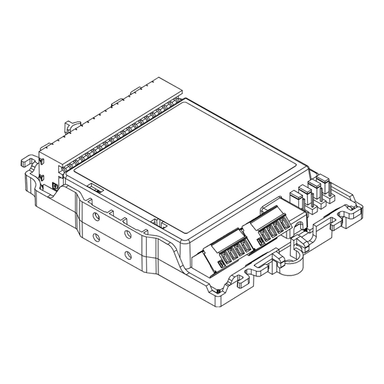
Setup and function Setup 3.2 Setup 3.2.1 Overview Figure 2: Overview of multi line separator module 1 Connector (20-pin) for sub-stub 5 Screw terminal for FDnet/C-NET lines detector line LINE 2 2 Module carrier 6 Screw terminal for FDnet/C-NET detector line LINE 1 3 Holes for mounting feet 7 Cable tie holder 4 Jumpers J1...J4... -
Page 18: Printed Circuit Board View
Setup and function Setup 3.2.2 Printed circuit board view Figure 3: Printed circuit board view of multi line separator module 1 LED line separator 1 10 Jumpers J1...J4 2 LED line separator 2 11 Screw terminal for FDnet/C-NET detector line LINE 2 12 Screw terminal for FDnet/C-NET 3 LED line separator 3 detector line LINE 1... -
Page 19: Adjustment Elements
3.2.4 Adjustment elements The multi line separator module has four jumpers, J1...J4. These jumpers can be used to configure whether the FDCL221-M is to be operated in one FDnet/C-NET loop or two FDnet/C-NET loops. Jumpers J1...J4 have the following two plug positions:... - Page 20 The multi line separator module is connected to a FDnet/C-NET loop. This is the default configuration of the multi line separator module when delivered. Figure 4: FDCL221-M topology with one detector line loop First sub-stub on FDnet/C-NET FDnet/C-NET device on sub-stub...
-
Page 21: Behaviour In Degraded Mode
Behaviour in degraded mode 2-loop operation The multi line separator module can be connected to two separate FDnet/C-NET loops. Figure 5: FDCL221-M topology with two detector line loops First sub-stub on FDnet/C-NET Fifth sub-stub on FDnet/C-NET loop 1 loop 2... -
Page 22: Accessories
● Compatible with: – Input module FDCI22x(-CN) – Input/output module FDCIO22x(-CN) – Output module FCA1209-Z1 – Multi line separator module FDCL221-M – Zone module, external powered FDCI223, FDCI723 – Sounder module FCA2005-A1 ● Order number: A5Q00003855 3.5.2 U-rail TS35 ●... -
Page 23: Housing Fdch221
Setup and function Accessories 3.5.3 Housing FDCH221 ● To protect against dust and wetness ● Compatible with: – Multi line separator module FDCL221-M – Input module FDCI22x(-CN) – Input/output module FDCIO22x(-CN) – Output module FCA1209-Z1 – Radio gateway FDCW241 –... -
Page 24: Connection Terminal Dbz1190-Ab
Setup and function Accessories 3.5.6 Connection terminal DBZ1190-AB ● Auxiliary terminal for connecting cables ● For T-branches of additional cabling, e.g., for cable shielding, detector heating units, sounder base, external alarm indicators, etc. ● For conductor cross-sections of 0.5…2.5 mm² ●... -
Page 25: Planning
FDnet/C-NET detector line, on which FDnet/C-NET devices (Tr/Ts) are installed with an integrated line separator function. The outgoing sub-stub lines are directly connected to the multi line separator modules FDCL221-M without a distributor terminal. 25 | 42 A6V10224006_g_en_--... - Page 26 Planning Accessories Placing the multi line separator module FDCL221-M in intermediate distributors e.g., on different floors Figure 7: FDCL221-M 1-loop operation or 2-loop operation assembled in an intermediate distributor Intermediate distributor First sub-stub on FDnet/C-NET loop 1 Fifth sub-stub on FDnet/C-NET...
-
Page 27: Compatibility
Depending on the type and software version of the control panel, the FDCL221-M may be shown in the control panel with another type designation (e.g., FDCL221). If using older control panels, the FDCL221-M can always be identified by its unique device ID. -
Page 28: Environmental Influences
Planning Environmental influences 4.4 Environmental influences If the devices are used in industrial applications, consultation with the project manager is required, since plastics do not withstand certain environmental conditions. The following factors must be taken into consideration: ● Chemicals ● Temperature ●... -
Page 29: Mounting / Installation
Mounting / Installation Mounting on U-rail or flat surface 5 Mounting / Installation The multi line separator module can be installed directly or in an additional housing. The additional housing FDCH221 must be ordered separately. See also 2 Housing FDCH221 [➙ 23] 5.1 Mounting on U-rail or flat surface The multi line separator module can be installed directly without additional housing in the following ways:... -
Page 30: Removing From The U-Rail
Mounting / Installation Removing from the U-rail Figure 9: Vertical or horizontal mounting on U-rail TS35 See also 2 Installation and connection diagram [➙ 32] 5.2 Removing from the U-rail Proceed as follows to remove the multi line separator module from the U-rail: 1. -
Page 31: Mounting With Housing Fdch221
Mounting / Installation Mounting with housing FDCH221 5.3 Mounting with housing FDCH221 The multi line separator module can be installed in a separate housing FDCH221. The housing protects the multi line separator module from dirt and dust. Proceed as follows to mount the multi line separator module in housing FDCH221: 1. -
Page 32: Installation And Connection Diagram
Specialist electrical engineering knowledge is required for installation. ● Only an expert is permitted to carry out installation work. Incorrect installation can take safety devices out of operation unbeknown to a layperson. Figure 12: FDCL221-M connection diagram 32 | 42 Building Technologies A6V10224006_g_en_-- Fire Safety... - Page 33 Press orange contact opening with screwdriver to loosen connection line from socket strip. Place nine line separators, each with an ID number, between sub-stub connections. Self-adhesive tear-off labels are available on the FDCL221-M for your system documentation (see following figure). Figure 13: Tear-off labels ●...
-
Page 34: Commissioning
6 Commissioning From a FDnet/C-NET communication point of view, the multi line separator module FDCL221-M is a line participant which, depending on the operation mode, occupies up to nine bus addresses and is visible in the line topology. Each individual line separator has its own bus address. -
Page 35: Maintenance / Troubleshooting
Maintenance / Troubleshooting 7 Maintenance / Troubleshooting The multi line separator module is maintenance-free. It features a self-monitoring function and must be replaced if damaged. 35 | 42 A6V10224006_g_en_-- Building Technologies Fire Safety 2018-10-25... -
Page 36: Specifications
Specifications Technical data 8 Specifications 8.1 Technical data You will find information on approvals, CE marking, and the relevant EU directives for this device (these devices) in the following document(s); see 'Applicable documents' chapter: ● Document A6V10230308 Detector line Operating voltage DC 12…33 V Quiescent current: ●... - Page 37 Specifications Technical data Line separator Line voltage: (per separator) ● Nominal DC 32 V (= V ● Minimum DC 12 V (= V ● Maximum DC 33 V (= V Voltage at which the separator opens: ● Minimum DC 7.5 V (= V SO min ●...
- Page 38 Dimensions (L x W x H): ● Module FDCL221-M 132 x 90 x 24 mm (without housing) ● Housing FDCH221 207 x 119 x 50 mm Weight of module FDCL221-M 0.124 kg Housing material Colors: ● Module carrier ∼RAL 9010 pure white ●...
-
Page 39: Dimensions
Specifications Dimensions 8.2 Dimensions Figure 14: Dimensions for different types of mounting without housing Figure 15: Dimensions for housing FDCH221 8.3 Environmental compatibility and disposal This equipment is manufactured using materials and procedures which comply with current environmental protection standards as best as possible. -
Page 40: Index
Index Index Numerics Impact 1-loop operation Chemicals............28 All 9 line separators in one detector line ..19 Moisture ............28 2-loop operation Temperature ........... 28 4 line separators each in one detector line ..19 Intended use ............ 5 Application area Jumper Ambient conditions ......... - Page 41 Index 41 | 42 A6V10224006_g_en_-- Building Technologies Fire Safety 2018-10-25...
- Page 42 Issued by © Siemens Switzerland Ltd, 2009 Siemens Switzerland Ltd Technical specifications and availability subject to change without notice. Building Technologies Division International Headquarters Theilerstrasse 1a CH-6300 Zug +41 58 724 2424 www.siemens.com/buildingtechnologies Document ID: A6V10224006_g_en_-- Edition: 2018-10-25...
Need help?
Do you have a question about the FDCL221-M and is the answer not in the manual?
Questions and answers