
Related Manuals for ASRock Industrial 4X4-7840U-1U


Summary of Contents for ASRock Industrial 4X4-7840U-1U
- Page 1 4X4-7840U-1U 4X4-7640U-1U User Manual Version 1.0 Published November 1, 2023 Copyright©2023 ASRockInd INC. All rights reserved.
- Page 2 Version 1.0 Published November, 2023 Copyright©2023 ASRockInd INC. All rights reserved. Copyright Notice: No part of this documentation may be reproduced, transcribed, transmitted, or translated in any language, in any form or by any means, except duplication of documentation by the purchaser for backup purpose, without written consent of ASRockInd Inc.
- Page 3 WARNING THIS PRODUCT CONTAINS A BUTTOON BATTERY If swallowed, a button battery can cause serious injury or death. Please keep batteries out of sight or reach of children. CALIFORNIA, USA ONLY The Lithium battery adopted on this motherboard contains Perchlorate, a toxic substance controlled in Perchlorate Best Management Practices (BMP) regulations passed by the California Legislature.
-
Page 4: Table Of Contents
Contents Chapter 1 Introduction Package Contents Specifications Motherboard Layout I/O Panel Block Diagram Chapter 2 Installation Screw Holes Pre-installation Precautions Installation of Memory Modules Expansion Slots Onboard Headers and Connectors Chapter 3 UEFI SETUP UTILITY Introduction 3.1.1 Entering BIOS Setup 3.1.2 UEFI Menu Bar 3.1.3... - Page 5 3.3.5 ACPI Configuration 3.3.6 USB Configuration 3.3.7 Trusted Computing Hardware Health Event Monitoring Screen Security Screen Boot Screen Exit Screen...
-
Page 6: Chapter 1 Introduction
If you require technical support related to this motherboard, please visit our website for specific information about the model you are using. https://www.asrockind.com/en-gb/technical-support 1.1 Package Contents ASRockInd 4X4-7840U-1U / 4X4-7640U-1U Motherboard (4X4 (4.09-in x 4.02-in x 1.4-in, 10.4 cm x 10.2 cm x 3.6 cm)) -
Page 7: Specifications
1.2 Specifications Form Factor Dimensions 4X4 (4.09-in x 4.02-in x 1.4-in, 10.4 cm x 10.2 cm x 3.6 cm) AMD Ryzen™ 7040U-Series Processor AMD Ryzen™ 7 7840U (Max Speed up to 5.1GHz) System AMD Ryzen™ 5 7640U (Max Speed up to 4.9GHz) BIOS AMI SPI 256 Mbit Technology... - Page 8 4X4-7840U-1U_4X4-7640U-1U Input PWR 12V~19V DC-In Jack Power AT/ATX supported Requirements Power On -AT: Directly PWR on as power input ready -ATX: Press button to PWR on after power input ready Operating 0ºC ~ 70ºC Temp Storage Temp -40° C ~ 85° C Environment Operating 5% ~ 90%...
-
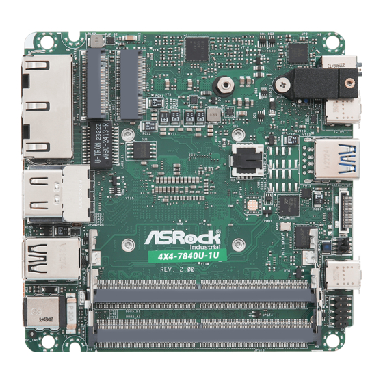
Page 9: Motherboard Layout
1.3 Motherboard Layout AUDIO1 M.2 SSD LAN1 M2E_1 (M2M_1) USB 4.0 (Type-C) TC_U4_1 LAN2 USB 3.2 Gen2 BIOS USB3_5 HDMI2 HDMI1 SATA3_1 Industrial USB 2.0: 4X4-7840U T: USB2_6 B: USB2_7 USB 4.0 (Type-C) TC_U4_2 DDR5_B1 (Support DDR5 Only) DC_IN1 PANEL1 DDR5_ 1 (Support DDR5 Only) 1 : M.2 Key-M Socket (M2M_1) 2 : M.2 Key-E Socket (M2E_1) - Page 10 4X4-7840U-1U_4X4-7640U-1U FAN1 PWR_BTN1 ESPI1 BAT1 Backside : 6 : Power Button (PWR_BTN1) 7 : Fan Connector (FAN1) 8 : Battery Connector (BAT1) 9 : ESPI Connector (ESPI1)
-
Page 11: I/O Panel
1.4 I/O Panel RJ45 LAN Port (LAN1)* USB 4 Type-C Port (TC_U4_2) RJ45 LAN Port (LAN2)** USB 3.2 Gen2 Port (USB3_5) (supports DASH function) USB 4 Type-C Port (TC_U4_1) HDMI Ports (HDMI1_2) Audio Jack (AUDIO1) USB 2.0 Ports (USB2_6_7) DC-In Jack (DC_IN1) * There are two LEDs next to the LAN1 ports. -
Page 12: Block Diagram
4X4-7840U-1U_4X4-7640U-1U 1.5 Block Diagram 4X4-7840U 4X4-7840U-1U 4X4-7640U-1U 4X4-7640U HDMI 1.4b 2 x HDMI Channel A DDR5 5600MHZ SO-DIMM Connector HDMI 1.4b Channel B DDR5 5600MHZ SO-DIMM USB4 USB4 Type-C KB8002 Connector PCIe Gen4 x4 M.2 Key M USB 2.0 Type-C... -
Page 13: Chapter 2 Installation
Chapter 2 Installation This is a 4X4 (4.09-in x 4.02-in x 1.4-in, 10.4 cm x 10.2 cm x 3.6 cm) form factor mother- board. Before you install the motherboard, study the configuration of your chassis to ensure that the motherboard fits into it. Make sure to unplug the power cord before installing or removing the motherboard. -
Page 14: Installation Of Memory Modules
4X4-7840U-1U_4X4-7640U-1U 2.3 Installation of Memory Modules 4X4-7840U-1U / 4X4-7640U-1U provides two 262-pin DDR5 (Double Data Rate 5) SO- DIMM slots, and supports Dual Channel Memory Technology. For dual channel configuration, you always need to install identical (the same brand, speed, size and chip-type) DDR5 DIMM pairs. -
Page 15: Expansion Slots
2.4 Expansion Slots There are 2 M.2 sockets on this motherboard. M.2 sockets: 1 x M.2 (Key E, 2230) with PCIe Gen4 x1, USB 2.0 for Wireless 1 x M.2 (Key M, 2242/2260/2280) with PCIe Gen4 x4 for SSD *M.2 Key M 2280 (supported by bracket) M.2 Key-M Socket (M2M_1) M.2 Key-E Socket (M2E_1) Signal Name... -
Page 16: Onboard Headers And Connectors
4X4-7840U-1U_4X4-7640U-1U 2.5 Onboard Headers and Connectors Onboard headers and connectors are NOT jumpers. Do NOT place jumper caps over these headers and connectors. Placing jumper caps over the headers and connectors will cause per- manent damage to the motherboard! SATA3 Port Signal Name (7-pin SATA3_1) R_SATA_TXP0... - Page 17 Connect the power switch, reset switch and system status indicator on the chassis to this header according to the pin assignments below. Note the positive and negative pins before connecting the cables. PWRBTN (Power Switch): Connect to the power switch on the chassis front panel. You may configure the way to turn off your system using the power switch.
- Page 18 4X4-7840U-1U_4X4-7640U-1U ESPI Connector Signal Name (20-pin ESPI1) ESPI_CLK (see p. 5, No. 9) ESPI_CS1# ESPI_RESET# The header is reserved for Port 80 code display and debugging purposes. SMB_CLK_MAIN_3V SMB_DATA_MAIN_3V ESPI_DAT0 ESPI_DAT1 ESPI_DAT2 ESPI_DAT3 +3VSB GPIO_TEST# ESPI_ALERT#...
-
Page 19: Chapter 3 Uefi Setup Utility
Chapter 3 UEFI SETUP UTILITY 3.1 Introduction ASRock Industrial UEFI (Unified Extensible Firmware Interface) is a BIOS utility which offers tweak-friendly options in an advanced viewing interface. The UEFI system works with a USB mouse and offers users a faster, sleeker experience. -
Page 20: Uefi Menu Bar
4X4-7840U-1U_4X4-7640U-1U 3.1.2 UEFI Menu Bar The top of the screen has a menu bar with the following selections: Main For setting system time/date information For advanced system configurations Advanced H/W Monitor Displays current hardware status Security For security settings Boot For configuring boot settings and boot priority Exit Exit the current screen or the UEFI Setup Utility... -
Page 21: Navigation Keys
3.1.3 Navigation Keys Use < > key or < > key to choose among the selections on the menu bar, and use < > key or < > key to move the cursor up or down to select items, then press <Enter> to get into the sub screen. -
Page 22: Main Screen (Advanced Mode)
4X4-7840U-1U_4X4-7640U-1U 3.2 Main Screen When you enter the UEFI SETUP UTILITY, the Main screen will appear and display the system overview. Because the UEFI software is constantly being updated, the following UEFI setup screens and descriptions are for reference purpose only, and they may not exactly match what you see on your screen. -
Page 23: Advanced Screen
3.3 Advanced Screen I n t h i s s ec t ion, you may s et t he con f ig u r at ions for t he fol low i ng items: CPU Configuration, Chipset Configuration, Storage Configuration, Super IO Configuration, ACPI Configuration, USB Configuration, and Trusted Computing. -
Page 24: Cpu Configuration
4X4-7840U-1U_4X4-7640U-1U 3.3.1 CPU Configuration PSS Support Enable/disable the generation of ACPI _PPC, _PSS, and _PCT objects. Core Performance Boost Core Performance Boost controls whether the processor transitions to a higher frequency than the processor's rated speed if the processor has available power and is within temperature specifications. -
Page 25: Chipset Configuration
3.3.2 Chipset Configuration IOMMU Enable/Disable IOMMU Support. Share Memory Share memory allows you to configure the size of memory that is allocated to the integrated graphics processor when the system boots up. Configuration options: [Auto] [64M] [128M] [256M] [512M] [1024M] [2048M] Options vary depending on the memory you use on your motherboard. - Page 26 4X4-7840U-1U_4X4-7640U-1U Onboard HD Audio This allows you to enable or disable the onboard HD audio. Configuration options: [Enabled] [Disabled] Onboard LAN1 This allows you to enable or disable the Onboard LAN1 feature. Configuration options: [Enabled] [Disabled] Onboard LAN2 This allows you to enable or disable the Onboard LAN2 feature. Configuration options: [Enabled] [Disabled] Restore on AC/Power Loss The option allows you to select the power state after a power failure.
-
Page 27: Storage Configuration
3.3.3 Storage Configuration Third Party SATA3 Controller The option allows you to enable or disable the SATA controllers. Configuration options: [Enabled] [Disabled] Third Party SATA3 Mode AHCI supports new features that improve performance. Configuration option: [AHCI] Hard Disk S.M.A.R.T. S.M.A.R.T stands for Self-Monitoring, Analysis, and Reporting Technology. It is a monitoring system for computer hard disk drives to detect and report on various indicators of reliability. -
Page 28: Super Io Configuration
4X4-7840U-1U_4X4-7640U-1U 3.3.4 Super IO Configuration WDT Timeout Reset Use the item to enable or disable Watch Dog Timer timeout to reset system. -
Page 29: Acpi Configuration
3.3.5 ACPI Configuration Onboard LAN Power On Use this item to enable or disable onboard LAN to turn on the system from the power-soft- off mode. Configuration options: [Enabled] [Disabled] RTC Alarm Power On RTC Alarm Power On allows the system to be waked up by the real time clock alarm. Set it to By OS to let it be handled by your operating system. -
Page 30: Usb Configuration
4X4-7840U-1U_4X4-7640U-1U 3.3.6 USB Configuration USB Power Control Use this option to control USB power. -
Page 31: Trusted Computing
3.3.7 Trusted Computing NOTE: Options vary depending on the version of your connected TPM module. Security Device Support Security Device Support allows you to enable or disable BIOS support for security device. O.S. will not show Security Device. TCG EFI protocol and INT1A interface will not be available. - Page 32 4X4-7840U-1U_4X4-7640U-1U Pending Operation Pending Operation allows you to schedule an Operation for the Security Device. NOTE: Your computer will reboot during restart in order to change State of the Device. Configuration options: [None] [TPM Clear] Platform Hierarchy This item allows you to enable or disable Platform Hierarchy. Configuration options: [Enabled] [Disabled] Storage Hierarchy This item allows you to enable or disable Storage Hierarchy.
-
Page 33: Hardware Health Event Monitoring Screen
3.4 Hardware Health Event Monitoring Screen This section allows you to monitor the status of the hardware on your system, including the parameters of the CPU temperature, motherboard temperature, fan speed, and the critical voltage. NOTE: Options vary depending on the features of your motherboard. CPU_Fan 1 Setting This item allows you to select a fan mode for CPU Fan 1. -
Page 34: Security Screen
4X4-7840U-1U_4X4-7640U-1U 3.5 Security Screen In this section you may set or change the supervisor/user password for the system. You may also clear the user password. Supervisor Password Set or change the password for the administrator account. Only the administrator has the authority to change the settings in the UEFI Setup Utility. -
Page 35: Boot Screen
3.6 Boot Screen This section displays the available devices on your system for you to configure the boot settings and the boot priority. Boot Option #1 The item allows you to set the system boot order. Boot From Onboard LAN The item allows the system to be waked up by the onboard LAN. -
Page 36: Exit Screen
4X4-7840U-1U_4X4-7640U-1U 3.7 Exit Screen Save Changes and Exit When you select this option, the following message “Save configuration changes and exit setup?” will pop out. Select [Yes] to save the changes and exit the UEFI SETUP UTILITY. Discard Changes and Exit When you select this option, the following message “Discard changes and exit setup?”...
Need help?
Do you have a question about the 4X4-7840U-1U and is the answer not in the manual?
Questions and answers