Table of Contents
Troubleshooting

Related Manuals for Miller INTEGRA 230


Summary of Contents for Miller INTEGRA 230
- Page 1 OM-195 565 September 1999 Effective with serial number: 230 - 151973 280 - 151974 Processes MIG (GMAW) Welding Flux Cored (FCAW) Welding Description INTEGRA 230 and 280 Visit our website at www.MillerWelds.com...
- Page 2 1929. This Owner’s Manual is designed to help you get the most out of your Miller products. Please take time to read the Safety precautions. They will help you protect yourself against potential hazards on the worksite. We’ve made installation and operation quick and easy.
-
Page 3: Table Of Contents
TABLE OF CONTENTS SECTION 1 – SAFETY PRECAUTIONS - READ BEFORE USING ..1-1. Symbol Usage ..........1-2. - Page 5 Declaration of Conformity “CE” Dichiarazione di Conformità Manufacturer’s Name: MILLER Europe S.p.A. Nome del Costruttore: Manufacturer’s Address: Via Privata Iseo, 6/E Indirizzo Costruttore: 20098 San Giuliano Milanese, Italy Declares that this product: INTEGRA 230 Dichiara che il Prodotto: INTEGRA 280 Conforms to the following Directives and Standards: È...
-
Page 7: Section 1 - Safety Precautions - Read Before Using
SECTION 1 – SAFETY PRECAUTIONS - READ BEFORE USING som _nd_4/98 1-1. Symbol Usage Means Warning! Watch Out! There are possible hazards with this procedure! The possible hazards are shown in the adjoining symbols. This group of symbols means Warning! Watch Out! possible Y Marks a special safety message. - Page 8 ARC RAYS can burn eyes and skin. BUILDUP OF GAS can injure or kill. D Shut off shielding gas supply when not in use. Arc rays from the welding process produce intense D Always ventilate confined spaces or use visible and invisible (ultraviolet and infrared) rays that can burn eyes and skin.
-
Page 9: Additional Symbols For Installation, Operation, And Maintenance
1-3. Additional Symbols For Installation, Operation, And Maintenance FIRE OR EXPLOSION hazard. MOVING PARTS can cause injury. D Do not install or place unit on, over, or near D Keep away from moving parts such as fans. combustible surfaces. D Keep all doors, panels, covers, and guards D Do not install unit near flammables. -
Page 10: Emf Information
1-5. EMF Information Considerations About Welding And The Effects Of Low Frequency 1. Keep cables close together by twisting or taping them. Electric And Magnetic Fields 2. Arrange cables to one side and away from the operator. Welding current, as it flows through welding cables, will cause electro- magnetic fields. -
Page 11: Section 2 - Specifications
SECTION 2 – SPECIFICATIONS 2-1. Specifications Amperes Input at Maximum Rated Load Output, 50 Dimensions Weight Open- Model Rated Welding Output or 60 Hz, Three-Phase Range DC Range DC Circuit Circuit Rating Rating (mm) (mm) (Kg) (Kg) Voltage DC 230 V 400 V 230 A @ 25.5 Volts DC, 35% Duty Cycle... -
Page 12: Volt-Ampere Curves
2-3. Volt-Ampere Curves The volt-ampere curves show the minimum and maximum voltage and amperage output capabilities of Model 230 the welding power source. Curves of other settings fall between the curves shown. Model 280 OM-195 565 Page 6... -
Page 13: Section 3 - Operation
SECTION 3 – OPERATION 3-1. Installing Welding Gun Drive Assembly Gun End Insert gun end through quick con- nect fitting on front panel, and tight- en ring nut until it is locked. Close door. Ref. ST-802 285-A 3-2. Installing Gas Supply Chain gas cylinder to running gear, wall, or other stationary support so cylinder cannot fall and break off... -
Page 14: Installing Wire Spool And Adjusting Hub Tension
3-3. Installing Wire Spool and Adjusting Hub Tension Use compression spring with 8 in (200 mm) spools. When a slight force is needed to turn spool, tension is set. Tools Needed: 15/16 in ST-072573-B 3-4. Electrical Service Guide Model 230 Model 280 Input Voltage Input Amperes At Rated Output... -
Page 15: Connecting Input Power
3-5. Connecting Input Power Check input voltage available at site. Input And Grounding Conductors Line Disconnect Device See Section 3-4. For non-CE three-phase operation: Y Always connect green wire to supply grounding termi- nal, never to a line terminal. Connect black, white, and red wires (L1, L2, L3) to line terminals. -
Page 16: Threading Welding Wire
3-6. Threading Welding Wire Wire Spool Welding Wire Inlet Wire Guide Pressure Adjustment Knob Drive Roll Outlet Wire Guide Gun Conduit Cable Lay gun cable out straight. Tools Needed: Ref. ST-802 285-A Hold wire tightly to keep it from unraveling. 6 in (150 mm) 4 in... -
Page 17: Section 4 - Operation
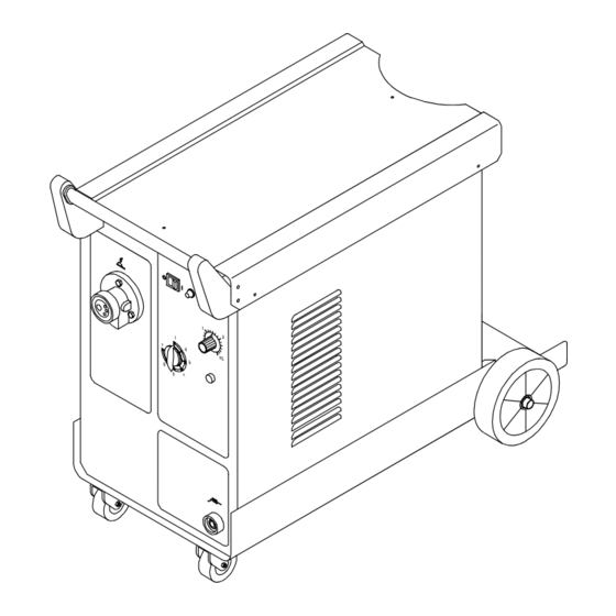
SECTION 4 – OPERATION 4-1. Controls Gun Connection See Section 3-1. Power Switch Indicator Light Indicator light is on when power is 280 Model Shown Wire Feed Speed Control Rotate control clockwise to in- crease wire feed speed. Overload Light Lights when unit overheats and shuts down (see Section 2-2). -
Page 18: Section 5 - Maintenance &Troubleshooting
SECTION 5 – MAINTENANCE &TROUBLESHOOTING 5-1. Routine Maintenance Y Disconnect power before maintaining. 3 Months Replace Repair or Clean unreadable replace tighten weld labels. cracked terminals. weld cable. 6 Months Blow out or vacuum inside. During heavy service, clean monthly. 5-2. -
Page 19: Troubleshooting
5-4. Troubleshooting Trouble Remedy No weld output; wire does not feed. Be sure line disconnect switch is On (see Section 3-5). Replace building line fuse or fuse F1 if open (see Section 3-5). Secure gun connections (see Section 3-1, and see gun Owner’s Manual). Have Factory Authorized Service Agent check Power switch. -
Page 20: Section 6 - Electrical Diagrams
SECTION 6 – ELECTRICAL DIAGRAMS Figure 6-1. Circuit Diagram (230 Model) OM-195 565 Page 14... - Page 21 Figure 6-2. Circuit Diagram (280 Model) OM-195 565 Page 15...
-
Page 22: Section 7 - Parts List
SECTION 7 – PARTS LIST Hardware is common and not available unless listed. Figure 7-1. Main Assembly 230 Model OM-195 565 Page 16... - Page 23 Qty. Qty. Item Ref. Code Item Ref. Code 156121008 ZE.0.0.9 O.L. 056072069 ZE.0.0.16 056126061 MQ.0.2.7 056076198 MU.0.0.39 1 156091025 ZE.0.0.25 057021018 ZE.0.3 056076199 MU.0.0.40 1 656102005 ZE.0.0.23 057014110 ZE.0.5 156122026 ZE.0.0.24 056054051 MQ.0.0.10 1 156118028 ZE.0.0.20 156006017 ZE.0.0.18 P.C.B. 057084080 ZE.0.1 058021108 ZE.1 057052010 MQ.0.1 057079029 ZE.0.4...
- Page 24 Hardware is common and not available unless listed. Figure 7-2. Main Assembly 280 Model OM-195 565 Page 18...
- Page 25 Qty. Qty. Item Ref. Code Item Ref. Code 156121008 ZE.0.0.9 056076198 MU.0.0.39 1 056126061 MQ.0.2.7 156091025 ZE.0.0.25 056076199 MU.0.0.40 1 057021018 ZE.0.3 057014110 ZE.0.5 656102005 ZE.0.0.23 056054051 MQ.0.0.10 1 156122026 ZE.0.0.24 156006017 ZE.0.0.18 156118028 ZE.0.0.20 058021108 ZE.1 P.C.B. 057084080 ZE.0.1 057079030 ZF.0.1 057052010 MQ.0.1 056067220 ZF.0.0.3...
- Page 26 Notes...
- Page 27 Effective January 1, 1999 This limited warranty supersedes all previous Miller warranties and is exclusive with no other guarantees or warranties expressed or implied. LIMITED WARRANTY – Subject to the terms and conditions APT, ZIPCUT & PLAZCUT Model Plasma Cutting below, Miller Electric Mfg.
- Page 28 Phone: 414-735-4505 USA & Canada FAX: 920-735-4134 International FAX: 920-735-4125 European Headquarters – United Kingdom Phone: 44 (0) 1204-593493 FAX: 44 (0) 1204-598066 Miller Europe Italy Phone: 39 (0) 2982901 PRINTED IN USA 1999 Miller Electric Mfg. Co. 7/99...
Need help?
Do you have a question about the INTEGRA 230 and is the answer not in the manual?
Questions and answers