
Related Manuals for National Instruments IMAQ PCI-1426


Summary of Contents for National Instruments IMAQ PCI-1426
- Page 1 IMAQ IMAQ PCI-1426 User Manual Base Configuration Camera Link Image Acquisition Device IMAQ PCI-1426 User Manual November 2004 374040A-01...
- Page 2 For further support information, refer to the Technical Support and Professional Services appendix. To comment on National Instruments documentation, refer to the National Instruments Web site at ni.com/info and enter the info code feedback. © 2004 National Instruments Corporation. All rights reserved.
- Page 3 The reader should consult National Instruments if errors are suspected. In no event shall National Instruments be liable for any damages arising out of or related to this document or the information contained in it.
- Page 4 These classes are known as Class A (for use in industrial-commercial locations only) or Class B (for use in residential or commercial locations). All National Instruments (NI) products are FCC Class A products. Depending on where it is operated, this Class A product could be subject to restrictions in the FCC rules. (In Canada, the Department of Communications (DOC), of Industry Canada, regulates wireless interference in much the same way.) Digital...
- Page 5 Conventions The following conventions are used in this manual: <> Angle brackets that contain numbers separated by an ellipsis represent a range of values associated with a bit or signal name—for example, DIO<3..0>. This icon denotes a note, which alerts you to important information. This icon denotes a caution, which advises you of precautions to take to avoid injury, data loss, or a system crash.
-
Page 6: Table Of Contents
About the IMAQ 1426 ....................1-1 Camera Link ........................1-2 Overview ......................1-2 Software Overview ......................1-3 NI-IMAQ Driver Software ................1-3 National Instruments Application Software ............1-4 Vision Builder for Automated Inspection.........1-4 Vision Development Module ............1-4 Integration with DAQ..................1-5 Integration with Vision and Motion ..............1-5... - Page 7 Serial Interface ....................3-8 Chapter 4 Signal Connections Connectors........................4-1 MDR 26-Pin Connector .................. 4-2 15-pin D-SUB Connector................4-2 Connector Signal Connection Descriptions ............ 4-3 Appendix A Cabling Appendix B Technical Support and Professional Services Glossary Index IMAQ PCI-1426 User Manual viii ni.com...
-
Page 8: About The Imaq 1426
These inputs can be individually selected in software. For more advanced digital or analog system triggering or digital I/O lines, you can use the IMAQ 1426 and NI-IMAQ with the National Instruments data acquisition (DAQ) or motion control product lines. -
Page 9: Camera Link
The IMAQ 1426 uses the Real-Time System Integration (RTSI) bus to solve this problem. The RTSI bus uses the National Instruments RTSI bus interface and ribbon cable to route additional timing and trigger signals between the IMAQ 1426 and up to four National Instruments DAQ, motion control, or IMAQ devices. -
Page 10: Software Overview
Chapter 1 Introduction Software Overview Programming the IMAQ 1426 requires the NI-IMAQ driver software for controlling the hardware. National Instruments also offers the following application software packages for analyzing and processing your acquired images. • NI Vision Builder for Automated Inspection—Allows you to configure solutions to common inspection tasks. -
Page 11: National Instruments Application Software
Chapter 1 Introduction National Instruments Application Software This section describes the National Instruments application software packages you can use to analyze and process the images you acquire with the IMAQ 1426. Vision Builder for Automated Inspection NI Vision Builder for Automated Inspection (AI) is configurable machine vision software that you can use to prototype, benchmark, and deploy applications. -
Page 12: Integration With Daq
You can then use LabVIEW to add functionality to the generated VI. Integration with DAQ Platforms that support NI-IMAQ also support NI-DAQ and a variety of National Instruments DAQ devices. This allows integration between IMAQ devices and National Instruments DAQ devices. Integration with Vision and Motion... -
Page 13: Installation
Installation This chapter contains a list of necessary and optional items to begin acquiring images with the IMAQ PCI-1426 device. This chapter also explains how to unpack, configure, and install the IMAQ 1426. What You Need to Get Started You need the following items to set up and use the IMAQ 1426: ❑... -
Page 14: Optional Equipment
Never touch the exposed pins of connectors. Remove the device from the package and inspect it for loose components or any other signs of damage. Notify National Instruments if the device appears damaged in any way. Do not install a damaged device in the computer. -
Page 15: Safety Information
If the device is damaged, turn it off and do not use it until service-trained personnel can check its safety. If necessary, return the device to National Instruments for repair. Keep away from live circuits. Do not remove equipment covers or shields unless you are trained to do so. -
Page 16: Installation
Installation Install the IMAQ 1426 in any open, compatible expansion slot in the PCI system. Refer to the IMAQ PCI-1426 Specifications for the typical power requirements for this device. The following instructions are for general installation. Consult the computer user manual or technical reference manual for specific instructions and warnings. -
Page 17: Configuring The Imaq 1426
IMAQ 1426 for acquisition. MAX, the National Instruments configuration utility, provides a simple interface for associating a camera file with the IMAQ 1426. Use the following guidelines to access the camera file in MAX: Launch MAX, and expand the Devices and Interfaces branch of the configuration tree. - Page 18 Chapter 2 Installation Many camera files are installed when you install NI-IMAQ, and many more are available for download from the National Instruments Camera Advisor . When installing new camera files, save them to the ni.com/camera folder located at Data...
-
Page 19: Hardware Overview
Hardware Overview This chapter provides an overview of IMAQ PCI-1426 hardware functionality and explains the operations of the device’s functional units. Functional Overview The IMAQ 1426 features a flexible, high-speed data path optimized for receiving and formatting video data from Camera Link cameras. -
Page 20: Camera Link And Imaq 1426
Exact timing of camera and image acquisition device communication is camera Note dependent. Refer to the Specifications of the Camera Link Interface Standard for Digital Cameras and Frame Grabbers manual for more information about Camera Link timing requirements. IMAQ PCI-1426 User Manual ni.com... -
Page 21: Hardware Binarization
0, while all pixels outside the threshold interval, or the background region, are set to the image white value. Figure 3-2 illustrates binarization and inverse binarization. NORMAL INVERSE Sampled Data Sampled Data Figure 3-2. Binarization and Inverse Binarization © National Instruments Corporation IMAQ PCI-1426 User Manual... -
Page 22: Multiple-Tap Data Formatter
I/O lines or, alternatively, as isolated or RS-422 input only lines. You can configure the four external triggers in any combination of single-ended I/O or input only lines. Table 3-1 lists the configuration options available for each trigger source. IMAQ PCI-1426 User Manual ni.com... -
Page 23: Wiring An Isolated Input To Output Devices
Caution than 30 VDC may damage the IMAQ 1426. Note Isolated inputs are compatible with 5 V logic if the external circuit meets the voltage and current requirements listed in the IMAQ PCI-1426 Specifications. Sensor Power PNP (Sourcing) Output Device... -
Page 24: High-Speed Timing
SDRAM. The IMAQ 1426 can perform ROI acquisitions on all video lines and frames. In an ROI acquisition, select an area within the acquisition window to transfer across the PCI bus to system memory. IMAQ PCI-1426 User Manual ni.com... -
Page 25: Scatter-Gather Dma Controllers
Bus Master PCI Interface The IMAQ 1426 implements the PCI interface with a National Instruments custom application-specific integrated circuit (ASIC), the PCI miniMITE. The PCI interface can transfer data at a theoretical maximum rate of 133 MB/s in bus master mode. -
Page 26: Serial Interface
IMAQ 1426 serial port and are not required for most users. National Instruments also fully supports the recommended serial API described in the Specifications of the Camera Link Interface Standard for Digital Cameras and Frame Grabbers manual. -
Page 27: Signal Connections
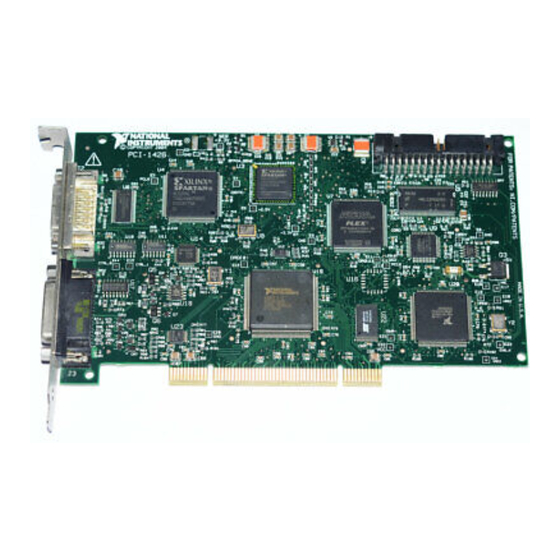
Signal Connections This chapter describes the MDR 26-pin connector and the 15-pin D-SUB connector on the IMAQ PCI-1426 device. Connectors Figure 4-1 shows the connectors on the IMAQ 1426 device. 1 MDR 26-Pin Connector 2 15-Pin D-SUB Connector Figure 4-1. IMAQ 1426 Connectors ©... -
Page 28: Mdr 26-Pin Connector
I/O available on this connector includes four TTL I/O lines, two optically isolated input lines, and two RS-422 input lines. National Instruments provides a generic 15-pin cable assembly kit (part number 190912-04) that breaks the connector out into 15 color-coded wires for easy connectivity. -
Page 29: Connector Signal Connection Descriptions
XCLK± Transmission clock on the Base configuration chip for Camera Link communication between the acquisition device and the camera. SerTC± Serial transmission to the camera from the image acquisition device. © National Instruments Corporation IMAQ PCI-1426 User Manual... - Page 30 Table 4-1. I/O Connector Signals (Continued) Signal Name Description SerTFG± Serial transmission to the frame grabber from the camera. CC<4..1>± Four LVDS pairs, defined as camera inputs and acquisition device outputs, reserved for camera control. On some cameras, the camera controls allow the acquisition device to control exposure time and frame rate.
-
Page 31: Appendix A Cabling
National Instruments provides a generic 15-pin cable assembly kit (part number 190912-04) that breaks the connector out into 15 color-coded wires for easy connectivity. Visit the National Instruments Web site at to purchase a cable assembly kit for the IMAQ 1426. - Page 32 Camera Link cables are manufactured by 3M corporation and are available from both National Instruments and 3M. Two-meter Camera Link cables (part number 187676-02) are available from the National Instruments Web site at . Camera ni.com/catalog Link cables are available in 1 to 10 m lengths from the 3M Web site at .
- Page 33 Technical Support and Professional Services Visit the following sections of the National Instruments Web site at for technical support and professional services: ni.com • Support—Online technical support resources at ni.com/support include the following: – Self-Help Resources—For answers and solutions, visit the...
- Page 34 You also can visit the Worldwide Offices section of to access the branch ni.com/niglobal office Web sites, which provide up-to-date contact information, support phone numbers, email addresses, and current events. IMAQ PCI-1426 User Manual ni.com...
- Page 35 Interface standard for digital video data and camera control based on the Channel Link chipset. Channel Link National Semiconductor chipset for high-speed data serialization and deserialization for transmission across cables up to 10 m. © National Instruments Corporation IMAQ PCI-1426 User Manual...
- Page 36 LVDS Low Voltage Differential Signaling (EIA-644). NI-IMAQ Driver software for National Instruments IMAQ hardware. Peripheral Component Interconnect. A high-performance expansion bus architecture originally developed by Intel to replace ISA and EISA. PCI offers a theoretical maximum transfer rate of 133 Mbytes/s.
- Page 37 Region of interest. A hardware-programmable rectangular portion of the acquisition window. RTSI bus Real-Time System Integration Bus. The National Instruments timing bus that connects IMAQ and DAQ devices directly, by means of connectors on the devices, for precise synchronization of functions.
- Page 38 Virtual Instrument. (1) A combination of hardware and/or software elements, typically used with a PC, that has the functionality of a classic stand-alone instrument. (2) A LabVIEW software module (VI), which consists of a front panel user interface and a block diagram program. IMAQ PCI-1426 User Manual ni.com...
- Page 39 (NI resources), B-2 overview, 4-2 Camera Link pin assignments (figure), 4-3 Base configuration, 3-2 cabling description, A-1 equipment, optional, 2-2 ordering information, A-2 examples (NI resources), B-1 overview, 1-2 CC<4..1>± signal (table), 4-4 © National Instruments Corporation IMAQ PCI-1426 User Manual...
- Page 40 3-4 configuration, 2-5 MDR 26-pin connector, 4-2 installation, 2-4 motion control, integrating with, 1-5 interfacing with, 2-5 multiple-tap data formatter, 3-3, 3-4 optional equipment, 2-2 overview and features, 1-1 requirements for getting started, 2-1 IMAQ PCI-1426 User Manual ni.com...
- Page 41 Index software programming choices, 1-3 integration with DAQ, 1-5 National Instruments application software, 1-4 National Instruments IMAQ Vision, 1-4 National Instruments support and NI Vision Builder for Automated services, B-1 Inspection, 1-4 NI support and services, B-1 NI Vision Development Module, 1-4...
Need help?
Do you have a question about the IMAQ PCI-1426 and is the answer not in the manual?
Questions and answers