Table of Contents
Advertisement
Quick Links
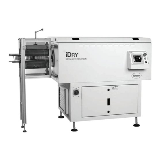
Nordson iDry
Series
®
Induction Dryers
Customer Product Manual
Document Number
1075452-05
Issued 09/23
For parts and technical support, call the Industrial Coating
Systems Customer Support Center at (800) 433-9319 or
contact your local Nordson representative.
This document is subject to change without notice.
Check
http://emanuals.nordson.com
for the latest version.
NORDSON CORPORATION • AMHERST, OHIO • USA
Advertisement
Table of Contents
Troubleshooting

Related Manuals for Nordson iDry Series


Summary of Contents for Nordson iDry Series
- Page 1 For parts and technical support, call the Industrial Coating Systems Customer Support Center at (800) 433-9319 or contact your local Nordson representative. This document is subject to change without notice. Check http://emanuals.nordson.com for the latest version. NORDSON CORPORATION • AMHERST, OHIO • USA...
-
Page 2: Table Of Contents
Nordson Corporation welcomes requests for information, comments, and This is a Nordson Corporation publication which is protected by copyright. inquiries about its products. General information about Nordson can be found on Original copyright date 2007. No part of this document may be photocopied,... - Page 3 Fuse Chart .................. Troubleshooting ................ Thermocouple Troubleshooting ..........Repair ..................Coil and Coil Tube Replacement ..........Thermocouple Replacement ............Air Filter Replacement ..............Parts.................... Celsius−Fahrenheit Temperature Table ........Conversion Equations ..............1075452-05 © 2023 Nordson Corporation...
- Page 4 1075452-05 © 2023 Nordson Corporation...
- Page 5 Change Record Change Record Revision Date Change 03/16 Ambient Temperature Compensation instructions added 09/23 Revised for TUV Compliance 1075452-05 © 2023 Nordson Corporation...
- Page 6 Change Record 1075452-05 © 2023 Nordson Corporation...
-
Page 7: Safety
Intended Use Use of Nordson equipment in ways other than those described in the documentation supplied with the equipment may result in injury to persons or damage to property. Some examples of unintended use of equipment include: •... -
Page 8: Regulations And Approvals
Regulations and Approvals Make sure all equipment is rated and approved for the environment in which it is used. Any approvals obtained for Nordson equipment will be voided if instructions for installation, operation, and service are not followed. Refer to the Declaration of Conformity for approvals standards. -
Page 9: High-Pressure Fluids
Nordson iDry® Series Induction Dryers • Obtain and read Safety Data Sheets (SDS) for all materials used. Follow the manufacturer’s instructions for safe handling and use of materials, and use recommended personal protection devices. • To prevent injury, be aware of less-obvious dangers in the workplace that often cannot... -
Page 10: Fire Safety
• Use only replacement parts that are designed for use with original equipment. Contact your Nordson representative for parts information and advice. WARNING: In the event of an electrical fire, use a Class C rated Fire Extinguisher or a multi-rated extinguisher that includes Class C rating. -
Page 11: Halogenated Hydrocarbon Solvent Hazards
Iodine “Iodo-” Check your material SDS or contact your material supplier for more information. If you must use halogenated hydrocarbon solvents, contact your Nordson representative for information about compatible Nordson components. Action in the Event of a Malfunction If a system or any equipment in a system malfunctions, shut off the system immediately and perform the following steps: •... -
Page 12: Action In The Event Of Serious Injury
Nordson iDry® Series Induction Dryers Action in the Event of Serious Injury Personal injury could occur when the induction dryer is in a normal operating mode and also in the event of a severe equipment malfunction. In normal operating conditions product may travel through various cage work transitions and conveying surfaces. -
Page 13: Equipment Grounding And Bonding
Nordson iDry® Series Induction Dryers Equipment Grounding and Bonding WARNING: Only properly trained personnel should be operating the induction dryer equipment WARNING: Proper grounding and bonding are an essential part of safe operation of the induction dryer. • The induction dryer uses a single point primary ground connection for sheet metal components as shown below. -
Page 14: Emi Exposure
Nordson iDry® Series Induction Dryers EMI Exposure Induction equipment generates a magnetic field which dissipates energy rapidly with increasing distance from the source. See safe zone distances in the Figure below. • Avoid wearing watches or rings near the induction field •... -
Page 15: Disposal
Nordson iDry® Series Induction Dryers Disposal Dispose of equipment and materials used in operation and servicing according to local codes. 1075452-05 © 2023 Nordson Corporation... -
Page 16: Caution And Warning Labels
These labels should not be removed. If they are damaged, worn, or otherwise illegible, please contact Nordson Corporation for replacements. Table 1 Label Information... - Page 17 Nordson iDry® Series Induction Dryers Item Location Labels Warnings Electrical Potential Hazard, High Voltage DANGER Use Lockout / Tagout Procedures when Servicing LOCKOUT / TAGOUT Capacitor REQUIRED BEFORE PERFORMING SERVICE ON THIS EQUIPMENT Access Panel CAUTION Internal Ground Ground Bonding Caution...
- Page 18 12 Nordson iDry® Series Induction Dryers Figure 3 Locations of Warning Labels on iDry Series Induction Dryer (Shown with Optional Magnet Separator) Figure 4 Locations of Warning Labels shown on iDry Series Induction Dryer (Back Side) 1075452-05 © 2023 Nordson Corporation...
-
Page 19: Description
Nordson iDry® Series Induction Dryers Description The Nordson iDry Series Induction Dryers provide simple, efficient, and uniform drying of water-based end-sealing compounds applied to can ends. The dryers use solid-state induction heating to generate heat within the can ends and dry the sealing compound, at line speeds of up to 2,200 ends a minute. -
Page 20: Dryer Components
14 Nordson iDry® Series Induction Dryers Dryer Components See Figure 6 and Figure 7. Table 3 Components and Descriptions Item Name Description Contains the induction coil, glass coil tube, auxiliary air heater, heater blower, and exhaust blower. The can ends travel through the glass tube and are heated by the induction coil. - Page 21 Nordson iDry® Series Induction Dryers Figure 6 iDry Series Induction Dryer (Shown with Optional Magnet Separator) Figure 7 iDry Series Induction Dryer (Back Side) 1075452-05 © 2023 Nordson Corporation...
-
Page 22: Theory Of Operation
16 Nordson iDry® Series Induction Dryers Theory of Operation See Figure 8 and Figure 9. The can ends move through a glass coil tube inside the coil tray. The tube is surrounded by the induction coil. As can ends enter the dryer, the motion sensor at the entrance signals the controller. - Page 23 Nordson iDry® Series Induction Dryers Motion Thermocouple Coil and Tube Sensor Assembly Pulse Output only when Product is in Motion Green and Yellow LED Yellow LED EMERGENCY EMERGENCY S S T T OP Coil Tray POWER POWER Feed Direction Exit...
-
Page 24: Safety Devices
18 Nordson iDry® Series Induction Dryers Safety Devices Table 4 Safety Devices Item Name Description Opening the coil tray lid will interrupt control voltage to the MCR (Master Control Relay) Coil Tray Lid and de-energize CR1 (Circuit Relay 1). All RF power will be removed from the inverter Interlock Switch system. -
Page 25: Programming
Programming Essentials Type of Control Brand Name Programming Requirement Touchscreen Pro-face GP Series One (1) Blank USB flash drive, 1GB or larger. Nordson Part 1604912 (OIT/HMI) Touchscreen Allen-Bradley ® One (1) Blank USB flash drive, 1GB or larger. Nordson Part 1604912... -
Page 26: Specifications
NOTE: If the equipment is to operate at an elevation of higher than the recommended altitude, it must be de-rated. Contact your Nordson representative. Power Requirements for Operation Refer to dryer utility tag for line voltage and frequency power requirements. -
Page 27: Model Numbers
Nordson iDry® Series Induction Dryers Model Numbers iDry-xx-xx Dryer Length Product Material and Lane and Separator Table 7 Model Numbers and Letters Code Description 54 in. (137.2 cm) length dryer 86.2 in. (219.0 cm) length dryer 98.2 in. (249.4 cm) length dryer 114.3 in (290.3 cm) length dryer... -
Page 28: Dimensions
22 Nordson iDry® Series Induction Dryers Dimensions 29.3 in. 54.0 in. 743.0 mm 1371.3 mm 46.1 in. 1170.5 mm Figure 11 iDry 4S-S0 and 4D-S0 86.2 in. 2189.4 mm 46.1 in. 1170.5 mm Figure 12 iDry 6S-S0 and 6D-S0 98.2 in. - Page 29 Nordson iDry® Series Induction Dryers 114.3 in. 2494.5 mm 46.1 in. 1170.5 mm Figure 14 iDry 9S-S0 and 9D-S0 22.1 in. 38.1 in. 560.5 mm 966.9mm 49.5 in. 1257.0 mm -S1 Separator -S3 Separator Figure 15 -S3 Separator and -S1 Separator 1075452-05 ©...
-
Page 30: Operating Sound Levels
24 Nordson iDry® Series Induction Dryers Operating Sound Levels See Figure 16. Measurements taken at 5 ft, 4 in. (1.6 m) above floor level. 39.4 in. (1.0 m) 74 dB TOP VIEW 74 dB 72 dB 39.4 in. (1.0 m) 39.4 in. -
Page 31: Installation
Nordson iDry® Series Induction Dryers Installation WARNING: Allow only qualified personnel to perform the following tasks. Follow the safety instructions in this document and all other related documentation. Inspection Inspect the dryer external surfaces for any shipping related damage. The iDry system glass and coils are packaged separately. Carefully unpack and inspect each glass and coil. -
Page 32: Coil Type
26 Nordson iDry® Series Induction Dryers Coil Type The coil(s) appearance may vary depending on the application power levels. Table 9 Coils Model Weight Monofilar Coil Single helix wrap of a conductor Bifilar Coil Dual helix wrap of two conductors... -
Page 33: Coil Inspection
Nordson iDry® Series Induction Dryers Coil Inspection The coil(s) should have no gouges or scrapes along the copper wire surfaces. Variations in the spacing of the wires is normal. The fiberglass coil form should be a continuous tube without cracks or deformity. -
Page 34: Lift Points
28 Nordson iDry® Series Induction Dryers Lift Points Always use the designated lift points when moving the iDry systems. Center of gravity 10.0 in. (254.0 mm) 26.1 in. (663.1 mm) Lift point Lift point Figure 19 Lift points for iDry 4S-S0 and 4D-S0... - Page 35 Nordson iDry® Series Induction Dryers Center of gravity Lift point 10.0 in. (254.0 mm) 71.0 in. 11.3 in. (1804.3 mm) (286.4 mm) Lift point Figure 22 Lift points for iDry 9S-S0 and 9D-S0 1075452-05 © 2023 Nordson Corporation...
-
Page 36: System Positioning And Mounting
30 Nordson iDry® Series Induction Dryers System Positioning and Mounting Always use the lift points shown in the Lift Points section of this manual. Flow Direction The dryer must be positioned so that can ends pass through it in the correct direction. - Page 37 Nordson iDry® Series Induction Dryers 3.9 in. (100 mm) Up to 3.3 in. (83 mm) 4.1 in. (105 mm) to 6.9 in. (175 mm) end sizes) end sizes) end sizes) 1/4-20 NCB 1/4-20 NCB 1/4-20 NCB Threaded Insert Threaded Insert...
-
Page 38: Coil And Tube Installation
32 Nordson iDry® Series Induction Dryers Coil and Tube Installation See Figure 25. Install the coil and glass coil tube as follows: 1. Disconnect and lockout power to the dryer. 2. Use a 5/16 in. hex wrench to unlock the locks at each end of the coil tray lid. Lift the lid to the full up position. - Page 39 Nordson iDry® Series Induction Dryers Figure 24 Coil and Tube Installation 1. Air heater and exhaust vent screws 3. Glass coil tube 5. Bus bar terminals (4 on each hub) 4. Coil 2. Cushion and hold-down screws 1075452-05 © 2023 Nordson Corporation...
-
Page 40: System Wiring
34 Nordson iDry® Series Induction Dryers System Wiring Schematics and Wiring Diagrams Refer to the Addendum to this manual for dryer schematics and wiring diagrams. Connect AC Operating Voltage See Figure 25 for power input connections. Refer to Specifications Section: Power Requirements for Operation. -
Page 41: External Interlock
CAUTION: Nordson engineering recommends that the external interlock be connected and enabled. Without the interlock, random line motion can cause the controller to apply power to the coil while the line is stopped, which could overheat and damage stationary can ends inside the coil. -
Page 42: External Interlock Monitoring Or Ignoring
36 Nordson iDry® Series Induction Dryers External Interlock Monitoring or Ignoring To enable the use of the external interlock, see the External Interlock Activation part of this manual. Optional Dryer Ready Status Contact See Figure 26. The status contact provides a Dryer Ready signal. It is used in conjunction with the external interlock. -
Page 43: Magnetic Separator (Optional)
Nordson iDry® Series Induction Dryers Magnetic Separator (Optional) Refer to the Magnetic Separator Adjustments instruction sheet, part number 1040053, for instructions on adjusting the magnetic separator for correct operation. Exhaust Ducting (Optional, Customer−Supplied) Small amounts of water vapor and hot air are released from the exhaust vents located on the entrance end and rear. -
Page 44: Setup
38 Nordson iDry® Series Induction Dryers Setup WARNING: Allow only qualified personnel to perform the following tasks. Follow the safety instructions in this document and all other related documentation. Setup consists of: • System functionality verification • Laser motion sensor sensitivity adjustment •... -
Page 45: System Functionality Test
5. Release the ESTOP button (if pressed) 6. Press the POWER button on the operator panel. The POWER button illuminates green. A Nordson Splash logo screen will appear for approximately 20 seconds, followed by the Automatic Mode operator screen. 1075452-05... -
Page 46: Initialization
40 Nordson iDry® Series Induction Dryers Initialization Figure 29 Testing screen 1. During initialization, the Dryer will: • Test that the Air Pressure Switch System is OFF • Test that the Air Heater Contactor is OFF • Energize the Blower Control Relay (typically CR1) •... - Page 47 Nordson iDry® Series Induction Dryers 3. At the entrance of the dryer, verify the motion sensor visible laser is projected down onto the product and the laser is not obstructed by cage work connected to the dryer. Move the product stick slightly by hand. The green LED should turn on and off as the peak of the product stick passes under the laser.
- Page 48 42 Nordson iDry® Series Induction Dryers 9. After 3 seconds of no motion sensor output transitions, the dryer will return to the idle mode. Additional activation of the motion sensor will begin the heating cycles. Do not heat products in the dryer for more than 15 seconds unless in production mode.
-
Page 49: Laser Motion Sensor Sensitivity Adjustment
Nordson iDry® Series Induction Dryers Laser Motion Sensor Sensitivity Adjustment WARNING: Laser radiation. Do not look directly into the laser beam or its reflection from can bodies. Doing so could result in serious eye injury. The SICK laser sensor focal point is adjustable between 30−60 mm from the sensor face. -
Page 50: Language Selection
Spanish, French, Italian, and German. 1. Press the green power button on the operator terminal to turn on the dryer. 2. The Nordson iDry splash screen appears, then the Auto screen. Figure 35 Auto Mode Screen 3. Touch the Menu button in the lower right-hand corner. The Navigation screen appears. - Page 51 Nordson iDry® Series Induction Dryers 4. Touch the LANGUAGE button. The Language Selection screen appears. The currently selected language is displayed at the top. Figure 37 Language Selection Screen 1075452-05 © 2023 Nordson Corporation...
-
Page 52: Timer And Ramp Settings
(motion detected). 1. Press the green power button on the operator terminal. 2. The Nordson iDry splash screen appears, then the Auto screen (Figure 35). 3. Touch the MENU button in the lower right-hand corner. The Navigation screen appears (Figure 36). -
Page 53: Ramp Timer Setting
Nordson iDry® Series Induction Dryers Figure 39 Manual Mode Screen 9. Run can ends through the dryer at the desired production speed. 10. The Manual Mode screen displays Actual Temperature and % Power. Use the Up or Down arrow keys to adjust the % Power until the ends exiting the dryer are at the target setpoint +/- 5 degrees. -
Page 54: Motion Timer Setting
48 Nordson iDry® Series Induction Dryers Motion Timer Setting The Motion Timer setting delays turning off coil power when can end motion stops. This prevents control cycling to ramp mode each time the line momentarily stops. The factory default setting is 3 seconds. Do not set the motion timer for more than 5 seconds. -
Page 55: External Interlock Activation
1. Touch the CONFIG button on the Navigation screen (Figure 36). The Option Setup screen appears. (This screen is password-protected by default, contact your Nordson representative). 2. Touch the EXTERNAL INTERLOCK TIMER field and set the desired time with the keypad. -
Page 56: Temperature Offset And Power Limit Settings
50 Nordson iDry® Series Induction Dryers Temperature Offset and Power Limit Settings Touch the OFFSET & LIMITS button on the Navigation screen (Figure 36). The Temperature Offset and Power Limits screen appears. This screen can be password- protected. Figure 41 Temperature Offset and Power Limits Screen Temperature Offset Temperature offset is used to alter display temperature versus input temperature. -
Page 57: Pid Control Settings
Nordson iDry® Series Induction Dryers PID Control Settings Touch the PID SETUP button on the Navigation screen (Figure 36). The PID Control screen appears. This screen can be password-protected. Figure 42 PID Control Screen For the dryer to control temperature properly, three parameters must be set: •... -
Page 58: Temperature Setpoint, Display, And Alarm Settings
52 Nordson iDry® Series Induction Dryers Temperature Setpoint, Display, and Alarm Settings Touch the TEMP SETUP button on the Navigation screen (Figure 36). The Temperature Setpoint, Display, and Alarms screen appears. This screen can be password-protected. Figure 43 Temperature Setpoint, Display, and Alarm Screen Product Temperature Setpoint This setting duplicates the setpoint display on the Auto Mode screen. -
Page 59: Configuration/ Option Setup
Nordson iDry® Series Induction Dryers Configuration/ Option Setup NOTE: The Options screen is password-protected by default. This screen should only be accessed by qualified personnel. If you do not have the password, contact your Nordson representative. Touch the CONFIG button on the Navigation screen (Figure 36). A keypad appears. Enter the password and touch the ENT key. -
Page 60: Operation
54 Nordson iDry® Series Induction Dryers Operation Allow only qualified personnel to perform the following tasks. Follow the safety instructions in this document and all other related documentation. The induction dryer is ONLY intended to heat and assist in drying a water-based coating on container lids (can lids). -
Page 61: Startup
Nordson iDry® Series Induction Dryers Startup 1. Turn the main disconnect switch to the ON position. 2. Make sure that the: • coil tray lid is closed and locked • enclosure doors are closed and locked • rear access panel is fastened into place •... -
Page 62: Auto Mode
56 Nordson iDry® Series Induction Dryers Auto Mode The default operating mode is Auto mode. The Auto mode screen automatically appears when the dryer is turned on. In Auto mode, the PID loop continually adjusts the power output to achieve the temperature setpoint. -
Page 63: Manual Mode
Nordson iDry® Series Induction Dryers Manual Mode The dryer can also be operated in Manual mode. The Manual mode screen can be password protected so that it cannot be accessed. Access is turned off by default. Refer to the SETUP section in this manual for accessing the Manual mode screen. -
Page 64: High And Low Alarms
58 Nordson iDry® Series Induction Dryers High and Low Alarms If the difference between the setpoint temperature and the actual temperature rises above the Alarm High deviation or falls below the Alarm Low deviation, the dryer will continue to operate for a preset period of time (Temperature Alarm Delay). If the actual temperature is still above or below the alarm setpoints when the delay timer runs out, a system fault will occur. -
Page 65: Faults
Nordson iDry® Series Induction Dryers Faults Touch the FAULT PAGE button to open the Fault screen (Figure 49). System faults are displayed in red. The problem must be corrected and the fault reset before restarting the system. Refer to Troubleshooting for fault descriptions and recommended corrections. - Page 66 60 Nordson iDry® Series Induction Dryers The Navigation screen provides access to the system settings, auto and manual screens, and operator language screen. Touching the MENU button on any screen will open this screen. NOTE: Some screens are password-protected. If they are protected they can be opened but the values they display cannot be changed.
-
Page 67: Ambient Temperature Compensation
Nordson iDry® Series Induction Dryers Ambient Temperature Compensation The ambient temperature compensation option allows the dryer to track ambient temperature changes in the plant and automatically adjust the ramp power setting. This is beneficial for plants seeing substantial temperature swings. - Page 68 62 Nordson iDry® Series Induction Dryers 3. See Figure 52. On the Setup screen, select the PRODUCT TEMP SETPOINT field and use the screen keypad to adjust the product temperature setting. 4. On the Setup screen, select the RAMP POWER field and use the screen keypad to adjust ramp power.
- Page 69 Nordson iDry® Series Induction Dryers Figure 53 Ramp/Motion Setup with Ambient Compensation Activated Figure 54 Auto Run Screen with Ambient Compensation Activated 1075452-05 © 2023 Nordson Corporation...
-
Page 70: How To Change The Setpoint Temperature From The Auto Run Screen
64 Nordson iDry® Series Induction Dryers How to Change the Setpoint Temperature from the Auto Run Screen 1. See Figure 55. Select the AMB/COMP button from the Auto Run screen. See Figure 56. 2. Select the ENTER NEW DATA from the Warning screen. -
Page 71: Ambient Temperature Comp. Cancellation
Nordson iDry® Series Induction Dryers Ambient Temperature Comp. Cancellation Ambient temperature compensation can be turned off at any time. NOTE: A password is required to perform the following procedure. 1. To cancel temperature compensation mode, select the MENU button to transfer to the Menu/Navigation screen. -
Page 72: Ambient Comp. Data Monitor
66 Nordson iDry® Series Induction Dryers Ambient Comp. Data Monitor Compensation data can be monitored to compare original presets to current settings. 1. Select the MENU button. 2. See Figure 58. From Menu screen select the PLC / IO button. -
Page 73: Shutdown
Nordson iDry® Series Induction Dryers Shutdown To shut down the dryer, press the OFF pushbutton on the operator panel. NOTE: While you can stop the dryer by pressing the EMERGENCY STOP button or by switching the main disconnect switch to the OFF position, you should use the OFF pushbutton, which provides a controlled shutdown. -
Page 74: Maintenance And Troubleshooting Requirements
Never attempt to operate the induction dryer with a secured panel or door in the open position. Only trained maintenance personnel should conduct any repairs. Please contact Nordson Customer Service for troubleshooting and repairs not covered in this product manual. -
Page 75: Maintenance
Some solvents may also have an adverse effect on the dryer’s exterior finish. If the glass tube is cracked, replace it with a new tube supplied by Nordson only. Different sizes and wall thicknesses are used depending on the can end size and the application. -
Page 76: Quarterly
70 Nordson iDry® Series Induction Dryers Quarterly Table 13 Quarterly Maintenance Item Procedure With power off, check all wiring connections for vibration loosening. Use the following torque ratings for each location: PCB connectors 4 in-lb (0.45 N•m) Terminal blocks 5 in-lb (0.57 N•m) Circuit breakers 6.5 in-lb (0.73 N•m) -
Page 77: Critical Voltage Measurements
Nordson iDry® Series Induction Dryers Critical Voltage Measurements Voltage measurements shown below are critical for proper operation of the Nordson induction dryer. Consult Nordson Engineering if the measured results are outside the specified ranges. Table 15 Voltage Measurements Location Component Description... - Page 78 72 Nordson iDry® Series Induction Dryers Table 16 Voltage Measurements, continued Location Component Description Voltage Description Measurement (5A) 380/480 to COM = Line Voltage, 2 Ph (5B) 30 V to 30 V = 32 Vac to 34 Vac TFR-1 Ferro-Resonant...
- Page 79 Nordson iDry® Series Induction Dryers PS-1 VDCr +24VDC 30KW +24V REGULATOR BD MADE IN USA 1072656A-PCB 24VDC-RETURN COMMON JUMPER D11D Front View 380V 480V TFR-1 Front View Figure 62 Voltage Measurement Locations, continued 1075452-05 © 2023 Nordson Corporation...
-
Page 80: Fuse Chart
74 Nordson iDry® Series Induction Dryers Fuse Chart Figure 63 iDry fuses 1075452-05 © 2023 Nordson Corporation... -
Page 81: Troubleshooting
Nordson iDry® Series Induction Dryers Troubleshooting These procedures cover only the most common problems that you may encounter. If you cannot solve the problem with the information given here, contact your local Nordson representative for help. WARNING: Allow only qualified personnel to perform the following tasks. Follow the safety instructions in this document and all other related documentation. - Page 82 76 Nordson iDry® Series Induction Dryers Problem Possible Cause Corrective Action Main disconnect off Turn main disconnect switch to ON position. Coil tray lid or control Close and lock lid and doors. Adjust door interlock switch. enclosure doors open 1. Dryer will not turn...
- Page 83 Nordson iDry® Series Induction Dryers Problem Possible Cause Corrective Action Ramp power setting too Adjust setting (Ramp Mode Power Level Adjustment). high Motion timer setting 11. PRODUCT TEMP cannot compensate for HIGH fault line jogging that keeps Adjust setting (Ramp Timer Setting).
-
Page 84: Thermocouple Troubleshooting
78 Nordson iDry® Series Induction Dryers Thermocouple Troubleshooting The iDry system monitors the integrity of the bi-metal thermocouple. If the thermocouple breaks the system shuts down and displays the error message on the screen below: Thermocouple Fault Message Figure 64 Auto Screen with Thermocouple Fault Switching to manual mode allows you to override the missing thermocouple input and continue to operate until you can replace the thermocouple. - Page 85 Nordson iDry® Series Induction Dryers Thermocouple Percentage Fault Message Power Setting Figure 65 Manual Screen with Thermocouple Fault 1075452-05 © 2023 Nordson Corporation...
-
Page 86: Repair
Electrical repairs should always be done by a qualified electrician with knowledge of high voltage systems. For help with repairs not covered in this manual, contact your Nordson representative. WARNING: Never disarm any diagnostic device including but not limited to the current sensor, overtemperature switches, air pressure switch, or coil tray lid safety switches. - Page 87 Nordson iDry® Series Induction Dryers Figure 66 Coil and Tube Replacement (Air Heater at Entrance End shown) 1. Air Heater 4. Nylon slotted screws 7. Coil 2. Vent housings 5. Hubs 8. Coil connections (typical) 3. Screws (4 on each hub) 6.
-
Page 88: Thermocouple Replacement
82 Nordson iDry® Series Induction Dryers 9. Unpack the new component(s) and carefully install the glass coil tube inside the coil. 10. Carefully install the coil and tube assembly in the coil tray, positioning the ends of the tube into the hubs. It does not matter which end of the coil is at the entrance or exit unless the coil is marked with the flow direction. -
Page 89: Air Filter Replacement
Nordson iDry® Series Induction Dryers Air Filter Replacement See Figure 68. To replace the filter, pull it out of the right side of the holder. Figure 68 Filter Replacement 1075452-05 © 2023 Nordson Corporation... -
Page 90: Parts
84 Nordson iDry® Series Induction Dryers Parts Refer to the Addendum to this manual for spare parts. Temperature Conversions Celsius−Fahrenheit Temperature Table Table 17 Celsius to Fahrenheit Celsius Fahrenheit 122.0 123.8 125.6 127.4 129.2 131.0 132.8 134.6 136.4 138.2 140.0 141.8... - Page 91 ____________________________ Jeremy Krone Engineering Manager Industrial Coating Systems Amherst, Ohio, USA Nordson Authorized Representative in the EU Contact: Operations Manager Industrial Coating Systems Nordson Deutschland GmbH Heinrich-Hertz-Straße 42-44 D-40699 Erkrath Nordson Corporation 555 Jackson Street, Amherst, Ohio, 44001, USA DOC12022-04...
- Page 92 Industrial Coating Systems Amherst, Ohio, USA Nordson Authorized Representative in the UK Contact: Technical Support Engineer Nordson UK Ltd.; Unit 10 Longstone Road Heald Green; Manchester, M22 5LB. England Nordson Corporation • 555 Jackson St, Amherst, Ohio 44001. USA DOC12045-01...
Need help?
Do you have a question about the iDry Series and is the answer not in the manual?
Questions and answers