Table of Contents
Advertisement
Quick Links
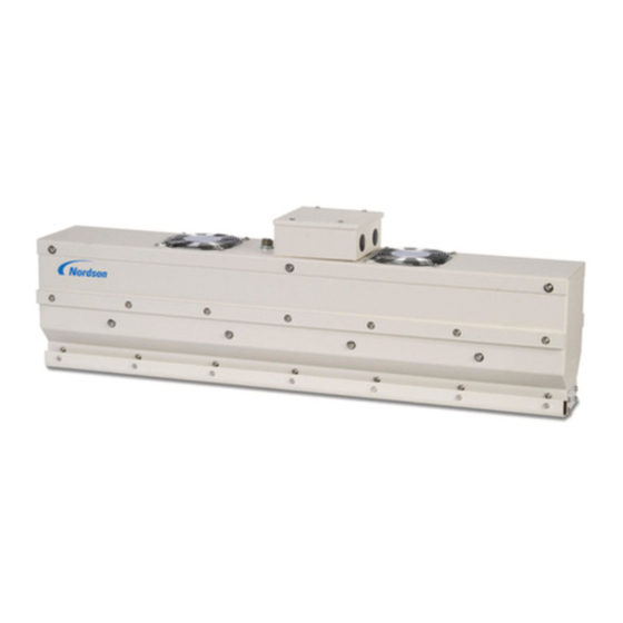
ISC2 Series Induction Dryers
Customer Product Manual
Part 1606739-01
Issued 01/15
For parts and technical support, call the
Finishing Customer Support Center at (800) 433-9319.
This document is subject to change without notice.
Check http://emanuals.nordson.com/finishing for the latest version.
NORDSON CORPORATION • AMHERST, OHIO • USA
Advertisement
Table of Contents

Subscribe to Our Youtube Channel
Related Manuals for Nordson ISC2 Series


Summary of Contents for Nordson ISC2 Series
- Page 1 Customer Product Manual Part 1606739-01 Issued 01/15 For parts and technical support, call the Finishing Customer Support Center at (800) 433-9319. This document is subject to change without notice. Check http://emanuals.nordson.com/finishing for the latest version. NORDSON CORPORATION • AMHERST, OHIO • USA...
-
Page 2: Table Of Contents
555 Jackson Street Amherst, OH 44001 Notice This is a Nordson Corporation publication which is protected by copyright. Original copyright date 2014. No part of this document may be photocopied, reproduced, or translated to another language without the prior written consent of Nordson Corporation. The information contained in this publication is subject to change without notice. - Page 3 Change Record Change Record Revision Date Change 01/15 New Release Part 1606739-01 E 2014 Nordson Corporation...
- Page 4 Change Record Part 1606739-01 E 2014 Nordson Corporation...
-
Page 5: Safety
Intended Use Use of Nordson equipment in ways other than those described in the documentation supplied with the equipment may result in injury to persons or damage to property. -
Page 6: Regulations And Approvals
Regulations and Approvals Make sure all equipment is rated and approved for the environment in which it is used. Any approvals obtained for Nordson equipment will be voided if instructions for installation, operation, and service are not followed. WARNING: Never disarm any diagnostic or interlock devices including but... -
Page 7: High-Pressure Fluids
ISC2 Series Induction Dryers High-Pressure Fluids High-pressure fluids, unless they are safely contained, are extremely hazardous. Always relieve fluid pressure before adjusting or servicing high pressure equipment. A jet of high-pressure fluid can cut like a knife and cause serious bodily injury, amputation, or death. Fluids penetrating the skin can also cause toxic poisoning. -
Page 8: Fire Safety
Clean, maintain, test, and repair equipment according to the instructions in your equipment documentation. Use only replacement parts that are designed for use with original equipment. Contact your Nordson representative for parts information and advice. Part 1606739-01 E 2014 Nordson Corporation... -
Page 9: Halogenated Hydrocarbon Solvent Hazards
“Iodo-” Check your material MSDS or contact your material supplier for more information. If you must use halogenated hydrocarbon solvents, contact your Nordson representative for information about compatible Nordson components. Action in the Event of a Malfunction If a system or any equipment in a system malfunctions, shut off the system immediately and perform the following steps: Disconnect and lock out system electrical power. -
Page 10: Description
ISC2 Series Induction Dryers Description The ISC2 Series induction systems provide simple, efficient, and uniform drying of side seam coatings and bottom spray coatings. The systems use solid state induction heating to generate heat within the can body, drying the coatings at various line speeds dependent on quantity of coil tray units. -
Page 11: Induction Dryer Components
Senses the product temperature at the exit end of the last coil tray. Product Flow Operator Control Pedestal Temperature Sensor Motion Sensor Coil Tray Control Enclosure/Power Supply Figure 2 ISC2 Series Induction Dryer (shown with one coil tray) Part 1606739-01 E 2014 Nordson Corporation... -
Page 12: Theory Of Operation
ISC2 Series Induction Dryers Theory of Operation The induction coil is connected to the power supply, and the can bodies travel below or above the coil. When the power supply applies an alternating current, the coil generates an alternating magnetic field that cuts through the side seam or dome of the can bodies dependent on the application. -
Page 13: Specifications
ISC2 Series Induction Dryers Specifications Manufacturing Data Code Serial Number: BK X X X X − X X X year month Operating Parameters Ambient temperature range: 5−45_C (40−112_F) Humidity: 0−70% for full system functionality Elevation (altitude): Less than 1524 m (5000 ft) Above 1524 m (5000 ft) system must be de-rated −... -
Page 14: Installation
Unpack and carefully inspect all components for obvious shipping damage and shortages. If any damage or shortages are observed, notify the shipper and your Nordson representative immediately. NOTE: A -in. hex wrench is required to unlock and lock the control enclosure doors. -
Page 15: System Positioning And Mounting
ISC2 Series Induction Dryers System Positioning and Mounting Flow Direction and Power Supply ISC2 coil trays are non-directional. 1. After coil trays are positioned on the line, install the motion sensor on the leading edge of first coil tray. NOTE: On lines with conveyor speed greater than 15 m/minute (16 ft/minute) the motion sensor should be positioned up stream. -
Page 16: Mounting And Line Connections
ISC2 Series Induction Dryers Mounting and Line Connections Coil trays Mount on adjustable mounts above or below the conveyor with the can bodies Make wiring connections using the wiring schematic in the addendum Power supply Install within 3 m (10 ft) of the first coil tray... -
Page 17: Coil Tray Installation
ISC2 Series Induction Dryers Coil Tray Installation 1. Connect the coil wiring to the terminals (1) located in the junction box (4) on lid of the coil tray (2). 2. Use the wiring schematics in the addendum to complete wiring connections. -
Page 18: Power Input
ISC2 Series Induction Dryers Power Input See Figure 5 for connections. Service requirement is 360-480 Vac 50 Hz or 440-480 Vac 60 Hz, 3 phase at 50 A. Class J fusing required. Systems are preset for voltage & frequency at the factory. Verify supply voltage with wiring schematics in the addendum. -
Page 19: External Interlock
CAUTION: Nordson engineering recommends that the external interlock be connected and enabled. Without the interlock, a random trip of the line motion sensor may cause the controller to apply power to the coil while the line is stopped, which could overheat stationary can bodies near the coil. -
Page 20: Disabling The External Interlock
ISC2 Series Induction Dryers Disabling the External Interlock If the external interlock will not be used, set the ISC2 system to run with the signal from the motion sensor only. 1. Use the touch screen to go to the Navigation screen. -
Page 21: Return Shipping Instructions
ISC2 Series Induction Dryers Return Shipping Instructions If required to return the ISC2 system, use the packing and shipping instructions below. Refer to Page 10 for lift points. Domestic/USA 1. Remove interconnect wiring from coil trays and individually wrap and pack each coil tray. -
Page 22: Setup
ISC2 Series Induction Dryers Setup WARNING: Allow only qualified personnel to perform the following tasks. Follow the safety instructions in this document and all other related documentation. Setup consists of the following: Motion sensor sensitivity adjustment Language selection Motion timer setting... -
Page 23: Language Selection
Spanish, French, Portuguese, German, Italian, and Dutch. 1. Press the green POWER button on the operator terminal to turn on the dryer. 2. See Figure 8. The Nordson iDryr splash screen appears, then the ISC2 Run screen. Figure 8 ISC2 Run Screen 3. - Page 24 ISC2 Series Induction Dryers 5. Touch the applicable language button to select the desired language. 6. Touch the MENU button to return to the Navigation screen. Figure 10 Language Selection Screen Part 1606739-01 E 2014 Nordson Corporation...
-
Page 25: Option Setup
Toggle any of the buttons to ON/OFF to control access for the various screens and functions. NOTE: The Allow Force Outputs function and the PLC I/O Display screen are reserved for Nordson service only. Figure 11 Option Setup Screen Restore System Defaults The default power up state is set to Keep Current Values. -
Page 26: Motion Sensor Sensitivity Adjustment
ISC2 Series Induction Dryers Motion Sensor Sensitivity Adjustment WARNING: Due to laser radiation exposure, do not look directly into the laser beam or its reflection from can bodies. Doing so could result in serious eye injury. See Figure 12. 1. The focal point is adjustable between 30-60 mm from the sensor face. -
Page 27: Timer And Motion Sensitivity Settings
ISC2 Series Induction Dryers Timer and Motion Sensitivity Settings See Figure 13. The settings for motion timer, motion detect sensitivity, and external interlock timer can be adjusted by selecting the applicable field on the Motion Timer screen, using the keypad to enter the desired setting, and selecting Ent to save the setting. -
Page 28: External Interlock Activation
ISC2 Series Induction Dryers External Interlock Activation The external interlock must be wired and activated before setting the timer. Refer to the Installation section for information on wiring. The following procedure details the settings required to use the interlock. 1. From the Navigation screen (Figure 9), select the Config button to bring up the Option Setup screen. -
Page 29: Temperature Offset Setting
ISC2 Series Induction Dryers Temperature Offset Setting See Figure 15. Temperature offset is used to alter the display temperature versus the input temperature. This is used to match the temperature to a master handheld temperature probe, or to alter the temperature output when using infrared type sensors when emissivity needs to be adjusted for various metal types. -
Page 30: Alarm And Temperature Display Settings
ISC2 Series Induction Dryers Alarm and Temperature Display Settings See Figure 16. From the Navigation screen, select Temp Setup to bring up the Temperature Display and Alarm screen. This screen can be password-protected. Select the applicable setting, then use the keypad to enter the desired setting. -
Page 31: Temperature Display Selection
ISC2 Series Induction Dryers Temperature Display Selection Touch the display field to toggle between C (Celsius) or F (Fahrenheit). Phase Control Select Systems including the optional phase control power system must select Phase Control On from the Option Setup screen (Figure 14). Standard control systems use pulse width modulation (PWM). -
Page 32: Line Speed Monitor Select
ISC2 Series Induction Dryers Line Speed Monitor Select See Figure 17. Power output to the coil trays can be controlled by the ISC2 system or remotely. Systems including the line speed monitor option utilize a 4−20mA input signal to control the power output into the coil trays. -
Page 33: Operation
ISC2 Series Induction Dryers Operation WARNING: Allow only qualified personnel to perform the following tasks. Follow the safety instructions in this document and all other related documentation. Operator Controls ISC2 controls consist of: Main disconnect (on power supply) Emergency stop switch... -
Page 34: Startup
ISC2 Series Induction Dryers Startup 1. Turn the main disconnect switch on the power supply to the ON position. 2. Check the following: Enclosure doors are closed and locked Rear access panel is fastened into place Emergency Stop switch is in the released position 3. -
Page 35: Isc2 Run Mode
ISC2 Series Induction Dryers ISC2 Run Mode See Figure 19. The default operating mode is ISC2 run mode. The ISC2 RUN screen automatically appears when the dryer is turned on. Figure 19 ISC2 Run Screen 1. Percent power bar graph 3. -
Page 36: High And Low Alarms
ISC2 Series Induction Dryers High and Low Alarms If the actual end temperature rises above the Alarm High setpoint or falls below the Alarm Low setpoint, the dryer will continue to operate for a preset period of time determined by the Temperature Alarm Delay. -
Page 37: Navigation Screen
ISC2 Series Induction Dryers Navigation Screen The Navigation screen provides access to the system settings, automatic and manual screens, and the operator language. Selecting the Menu button on any screen will open the Navigation screen. NOTE: Some screens are password protected. If they are protected, they can be opened, but the values they display cannot be changed. -
Page 38: Maintenance
ISC2 Series Induction Dryers Maintenance WARNING: Allow only qualified personnel to perform the following tasks. Follow the safety instructions in this document and all other related documentation. WARNING: HIGH VOLTAGE! Disconnect and lockout all power to the dryer before working inside the coil tray or control enclosure. Failure to observe may result in fatal injury to personnel. -
Page 39: Troubleshooting
ISC2 Series Induction Dryers Troubleshooting These troubleshooting procedures cover only the most common problems. If you cannot solve a problem with the information given here, contact your local Nordson representative for help. WARNING: Allow only qualified personnel to perform the following tasks. - Page 40 ISC2 Series Induction Dryers Problem Possible Cause Corrective Action COOLING AIR FAIL Obstructed or dirty air filter Remove any obstructions that might fault impede air flow. Replace filter if dirty. Fuse F8 open Test fuse and replace if blown. Rear access panel loose or Install access panel properly.
-
Page 41: Repair
Most repairs require no more than basic tools. Electrical repairs should always be done by a qualified electrician with knowledge of high voltage systems. For help with repairs not covered in this manual, contact your Nordson representative. WARNING: Never disarm any diagnostic device, including but not limited to the current sensor, overtemperature switches, air pressure switch, or coil tray lid safety switches. -
Page 42: Parts
ISC2 Series Induction Dryers Parts Refer to the addendum to this manual for spare parts. To order parts, call the Nordson Finishing Customer Support Center at (800) 433-9319 or contact your local Nordson representative. Temperature Conversions Celsius−Fahrenheit Temperature Table Celsius Fahrenheit 122.0... - Page 43 The product specified conforms to the directive and standards described above. _____________________ Hallie Smith-Petee Date : 12 Jan 2015 Engineering Manager Industrial Coating Systems Nordson Authorized Representative in the EU Person authorized to compile the relevant technical documentation. Contact: Operations Manager Industrial Coating Systems Nordson Deutschland GmbH...
Need help?
Do you have a question about the ISC2 Series and is the answer not in the manual?
Questions and answers