
Subscribe to Our Youtube Channel
Related Manuals for Dynapac VB 340V


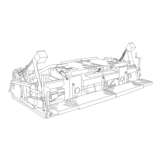
Summary of Contents for Dynapac VB 340V
- Page 1 OPERATION & MAINTENANCE Screed VB 340V VB 340TV Keep this manual for future reference Order number for this manual: D900981477 02-0508 270....275....
- Page 2 VALUE QUALITY THE ORIGINAL Your Authorized Dynapac Dealer:...
-
Page 3: Table Of Contents
Adjustment/equipment features ..............7 Compacting system ................... 7 Gas heater system ..................8 Electric heater VB 340V ................9 Electric heater VB 340TV ................9 Location of instruction labels and tpe plates ..........10 Screed type plate (1) ................11 Liquefied gas system type plate (2) ............ - Page 4 Operation ................. 1 Notes regarding safety ................1 Operation of the screed ................2 Extend/retract screed ................. 2 Adjusting the tamper (o) ................3 Adjusting the vibration ................3 Tamper/vibration frequency displays (o) (6) / (7) ........4 Operation of the gas heater system with flame monitoring ......5 Switch cabinet for screed heating system ..........
- Page 5 Set-up and modification ............1 Notes regarding safety ................1 General assembly ..................2 Fitting screed to finisher ................2 Mounting the side shields ................3 Hydraulic connections ................4 Position and designation of the connections: ........4 Electrical connections ................5 Extending the screed .................
- Page 6 Maintenance ................1 Notes regarding safety ................1 Maintenance intervals - screed in general ..........2 Maintenance intervals - gas system ............3 Maintenance intervals - electric heating system ........4 Lubrication points ..................5 Guide tubes ....................5 Other lubricating and maintenance points ..........6 Checkpoints ....................
-
Page 7: Preface
In the interest of continued development, the manufacturer reserves the right to make changes to the machine (which will not, however, change the essential features of the type of machine described) without updating the present operating instructions at the same time. Dynapac GmbH Wardenburg Ammerländer Strasse 93 D-26203 Wardenburg / Germany... -
Page 8: General Safety Instructions
The following alerts, prohibitions and instructions refer to the risks to which people, machinery and environment are exposed. Ignoring these instructions, bans and commands may lead to fatal injuries! Furthermore, the Dynapac publication "Directives for the correct and specified appli- cation of pavers" shall also be observed. Warning instructions... - Page 9 Attention: risk of hand injury! Attention: hot surfaces or hot liquids! Warning, risk of falling off! Attention: hazardous batteries! Attention: materials harmful to health and irritating substances! Attention: flammable materials! Attention: gas bottles!
-
Page 10: Prohibitive Signs
Do not sprinkle with water! Do not extinguish with water! Do-it-yourself maintenance is prohibited! Maintenance can be performed by skilled professionals only! Contact the Dynapac service! Danger of fire: do not use open flame and no smoking! Do not turn on! -
Page 11: Protective Gear
Protective gear The applicable local regulations may define the use of different protective gear! Observe these specifications! Protect your eyes with googles! Wear appropriate head protection! Protect your hearing with appropriate ear mufflers! Protect your feet with safety footwear! Always wear tight, conforming working coveralls! Wear visibility vest for good visibility! In case of polluted air, wear respiratory mask! -
Page 12: Environmental Protection
Environmental protection The locally applicable acts, directives and waste disposal regulations shall be ob- served, even if the attention is not specifically directed to these. During cleaning, maintenance and repair operation the materials polluting water e.g.: - lubricants (oils, grease) - hydraulic oil - gas oil - coolant... -
Page 13: Further Instructions
Further instructions Observe the manufacturer's and other instructions! e.g. the maintenance instructions of the engine manufacturer Description / figure in case of an electrically heated design! Description / figure in case of an electrically heated design! -
Page 15: A Correct Use And Application
The “Guidelines for the Correct Use and Application of Paver finishers” compiled by Dynapac are included in the scope of delivery for the present machine. The guide- lines are part of the present operating instructions and must always be heeded. Na- tional regulations are fully applicable. -
Page 17: B Description Of The Screed
B Description of the screed Application The Dynapac VB340 screed is operated in conjunction with a paver finisher. The screed is used for laying: - bitumen materials, - roll-down concrete or lean-mixed concrete, - track-laying ballast or - unbound mineral aggregates for foundations for paving. -
Page 18: Assemblies
Assemblies Tamper and vibration elements: The tamper knives converging in the middle area prevent seams in the middle. Auxiliary vibration (option) supports the compacting process, thus improving the tex- ture. The tamper and the vibration elements can be individually switched on and off and controlled with regard to speed. - Page 19 Screed heater system: Two different heater systems are available as options: Gas heater: The propane gas flame band heater features a tried-and-tested design and is easy to handle. The electronic temperature and flame monitoring system ensures short heating times and constant temperatures. Air guides to the tamper knives and side plates ensure efficient use of heat.
-
Page 20: Safety
Safety The safety devices of the paver finisher and of the screed are described in chapter B, section 3 of the operating instructions for the finisher. Remaining risks at the screed Danger of squeezing! At all moving parts of the screed, there is a danger of crushing, trap- ping or shearing. - Page 21 Danger of burning! Heating the screed heater leads to danger due to hot surfaces, par- ticularly on the bottom plates and side shields. Keep away from these parts! Or wear protective gloves! - Always wear all protective clothing required! Failure to wear protective clothing or wearing protective clothing in an improper manner can be dangerous to health.
-
Page 22: Technical Data
Technical data Dimensions VB340V VB340TV Basic width 1,70 1,70 Working width: min. width with 2 cut-off shoes 1,20 1,20 hydraulically extendable to 3,40 3,40 Depth of the bottom plates: basic screed extendable parts As regards extension of the screed, refer to the chapter entitled „Set-up and modifi- cation“. -
Page 23: Adjustment/Equipment Features
Adjustment/equipment features Crowning: - Adjustment range -2%... +4 % - Adjusting mechanism with ratchet via chain Height/angle adjustment of extendable parts Separate systems Hinged walkway plate Standard Lubrication system Individual lubrication points Compacting system Tamper system Vertical impact tamper Tamper stroke max. 3,5 mm Tamper frequency 0 ... -
Page 24: Gas Heater System
Gas heater system Fuel (liquefied gas) Propane gas Burner type Pipe burner Electronic ignition, Heater control system temperature monitoring, (switch cabinet on the screed) flame monitoring Gas bottles (on the screed) 1 units - Capacity per bottle 70 l - Gross weight per bottle 33 kg Operating pressure (downstream of pressure Approx. -
Page 25: Electric Heater Vb 340V
Electric heater VB 340V Electric heater with heating Type of heater strips in bottom plates Number of heating strips Units - Per bottom plate Screed heating system total output: - Main screed - bottom plate 1100 - Extendable part - bottom plate... -
Page 26: Location Of Instruction Labels And Tpe Plates
Location of instruction labels and tpe plates VB340.wmf Pos. Designation Screed type plate Gas system type plate * Bottle valve operating instructions * Warning plate „Hot surfaces“ Safety seymbols „Danger of electrical voltage“** Electric heater operating instructions** With „gas heater“ equipment only With „electric heater“... -
Page 27: Screed Type Plate (1)
Screed type plate (1) Typ_Bohl3.tif Pos. Designation Screed type Maximum operating weight of the screed Screed number Year of manufacture Manufacturer B 11... -
Page 28: Liquefied Gas System Type Plate (2)
Liquefied gas system type plate (2) GASANL3.TIF Pos. Designation Year of manufacture Type of gas to be used Connection overpressure in mbar Average gas consumption of the installed screed, in kg/h Average gas consumption of the screed extension parts, in kg/h Maximum permissible mass flow of the installed hose rupture protection in kg/h B 12... -
Page 29: C Transportation
C Transportation Safety regulations for transportation Accidents may occur when the paver finisher and the screed are not properly pre- pared for transportation or when transportation is carried out improperly! Retract the extension parts of the screed to the basic width and remove all extension parts that may have been attached. -
Page 30: Transporting The Removed Screed
Transporting the removed screed The procedure required to load and transport the screed when installed on the fin- isher is described in the operating instructions for the finisher. The screed must be retracted to the basic width. All protruding or loose parts and the gas bottles for the screed heating system (o) (see Chapters E and D) must be re- moved. -
Page 31: D Operation
D Operation Notes regarding safety Improper operation of the screed or the screed heater can endanger persons. - Ensure that all protective devices and covers are available and appropriately se- cured! - Immediately rectify any damage which is determined! Operation must not be con- tinued when the machine is defective! - Always ensure that no person is endangered when working! - Do not let any person ride along on the screed! -
Page 32: Operation Of The Screed
Operation of the screed For all general functions of the finisher and the screed that are not specially re- lated to the present screed, refer to the operating instructions of the finisher. Extend/retract screed To extend or retract the hydraulically ad- justable extension parts, - actuate the switch (1) on the remote controls installed on the right-hand... -
Page 33: Adjusting The Tamper (O)
2.2 Adjusting the tamper (o) The tamper function is switched on and off using the switch (2) on the finisher's operating panel (see finisher operating instructions). (o Pavers equipped with PLC system: Button (2a)) The tamper frequency (number of strokes a minute) is set using the speed regulator for the tamper (4). -
Page 34: Tamper/Vibration Frequency Displays (O) (6) / (7)
Tamper/vibration frequency displays (o) (6) / (7) The display can be used to optimaly ad- just the tamper and vibration speed to different paving situations. When the ignition is switched on, the rel- evant frequency is automatically dis- played (range 0 to maximum). During paving, the frequencies can be easily checked and, if necessary, read- justed using the rotary knobs (4),(5). -
Page 35: Operation Of The Gas Heater System With Flame Monitoring
Operation of the gas heater system with flame monitoring Switch cabinet for screed heating system... - Page 36 Pos. Designation Heating system master switch ON/OFF - Position 1: Heating system ON (o) and tamper/vibration speed dis- plays ON - Position 0: Heating system OFF (o) and speed displays OFF Controller for high/low temperature pre-selection, basic screed Controller for high/low temperature pre-selection, extendable parts Operating display, green Left middle section operating display, yellow Left extendable part operating display, yellow...
-
Page 37: Gas Supply Diagram
Gas supply diagram Gaslauf_EB51.bmp Pos. Designation Gas bottles Bottle valves Pressure reducer with pressure gauge Hose rupture protection devices Flame band burner Solenoid valves... -
Page 38: General Notes On The Gas Heater System
General notes on the gas heater system The heater of the screed burns propane gas (liquefied gas). The gas bottle stands on the finisher. The heater is equipped with an electron- ic flame and a temperature monitoring system. GHeiz_340.cdr Heed the following points before com- missioning the heater system: - The gas bottles must always be in the position provided for this purpose on... -
Page 39: Connection And Leak Test
Connection and leak test The gas pipe system of the basic screed and the extendable parts is permanently installed. To connect the gas bottles: - Unscrew the protective caps from the bottle valves and screw onto the rear of the bottle bracket. - Check whether the quick action valves are closed. -
Page 40: Commissioning And Checking The Heating System
Commissioning and checking the heating system The gas heating system is operated with two gas bottles. - Check whether the battery master switch is switched on. - Open the bottle valves (30). Unlock the safety valve by pressing the hose rupture protection device (29). -
Page 41: Function Of The Flame Monitoring System
Function of the flame monitoring system Pos. Designation Operating display, green Left middle section operating display, yellow Left extendable part operating display, yellow Right middle section operating display, yellow Right extendable part operating display, yellow Left middle section malfunction display, red Left extendable part malfunction display, red Right middle section malfunction display, red Right extendable part malfunction display, red... -
Page 42: Setting The Temperature Level
Via the temperature sensor and flame monitoring system, the electronics monitor gas heater operation. If there is no stable flame at the ignition burner within 7 seconds, the electronics indicate a malfunction. The gas supply is interrupted and the red indi- cator lamps on the ignition box and in the switch cabinet light up. -
Page 43: Switching Off The Heater
Switching off the heater After work has been completed, or when the heater is no longer required: - Switch off the On/Off switch (8) in the switch cabinet. - Close the quick action valves and both bottle valves (30). If these valves are not closed, there is a danger of fire and explosion due to the possible escape of uncombusted gas! Always close the valves during breaks... -
Page 44: Operating The Electric Heater
Operating the electric heater Switch cabinet for screed heating system 4 x 230 V Schalttafel_340E.wmf 29 30 The arrangement of the individual elements may vary slightly! D 14... - Page 45 Item Designation EMERGENCY STOP button Check button for insulation monitoring and insulation error pilot lamp Insulation monitoring reset button Generator telltale lamp Heating ON/OFF Circuit breaker for heating section 1 Circuit breaker for heating section 2 Circuit breaker for heating section 3 Circuit breaker for heating section 4 Heating section 1 telltale lamp Heating section 2 telltale lamp...
-
Page 46: General Information On The Heating System
General information on the heating system The electric heating system is supplied with power by a generator on board the paver which is controlled fully-automati- cally controlled in accordance with re- quirements. Heating resistors in the form of heating strips ensure direct temperature transi- tion and even distribution of heat. -
Page 47: Isolation Monitor
Isolation monitor The function of the protective insulation monitoring measure must be checked every day before starting work. This check only checks the function of the insulation monitor, not whether an in- sulation fault has occurred on the heat- ing sections or consumers. - Start the paver's engine. -
Page 48: Insulation Faults
Insulation faults If an insulation fault occurs during operation, and the indicator lamp displays an insu- lation fault, the operator may proceed as follows: - Switch the switches of all external equipment and the heating system to OFF and press the reset button for at least 3 seconds to delete the fault. - If the indicator lamp does not go out, the fault lies in the generator. -
Page 49: Commissioning And Checking The Heating System
Commissioning and checking the heating system In order to reach the required tempera- ture, the heating system should be switched on approx. 15 - 20 minutes be- fore the start of paving. - Switch on the paver's engine. - Switch on heating system ON / OFF switch (1). -
Page 50: Temperature Display, Setting Temperature Level
Temperature display, setting temperature level The temperature display and temperature level setting for the individual screed elements are carried out via the control and monitoring unit in the screed heat- ing system's switch cabinet. Operating the control and monitoring unit STC20002.bmp D 20... - Page 51 Pos. Designation / function Display. Nominal and actual temperature display. Fault code display. Auto / OFF button - Starts and stops the system. When in the „OFF“ switch position, „OFF“ is shown in the display. Increase in nominal temperature on the selected screed section. - If pressed briefly, the current temperature setting for the selected screed section is displayed.
-
Page 52: Temperature Setting
Temperature setting - Select screed section by pressing but- ton. - Depending on the desired tempera- ture change, press button (3) or (4). - The current nominal temperature is shown first. Adjustment in the corre- sponding direction is undertaken after 1.5 seconds. -
Page 53: Switching Off The Heating System
Switching off the heating system At the end of work or when the heating system is not required: - Switch off ON/OFF switch (1) of heat- ing system. Schalttafel_340E.wmf D 23... -
Page 54: Malfunctions
Malfunctions Problems during paving Problem Cause - change in the material temperature, demixing - wrong material composition - incorrect operation of the roller - incorrectly prepared foundation - long standstill times between loads - grade control reference line is not suitable - grade control jumps to the reference line - grade control toggles between up and down Wavy surface... - Page 55 Problem Cause - material temperature Cracks in the lay- - cold screed er (centre strip) - bottom plates are worn or warped - wrong crowning - material temperature - screed extension parts are incorrectly installed Cracks in the lay- - limit switch is not correctly set er (outer strip) - cold screed - bottom plates are worn or warped...
-
Page 56: Malfunctions On The Screed
Malfunctions on the screed Malfunction Cause Remedy Tamper is obstructed by cold Properly heat the screed bitumen Hydraulic oil level in the tank Top up the oil is too low Replace the valve; if neces- Pressure limiting valve is de- sary, repair and adjust the Tamper or vibra- fective... -
Page 57: E Set-Up And Modification
E Set-up and modification Notes regarding safety Inadvertent starting of the paver finisher can endanger persons working on the screed. Only carry out such work with the finisher motor at a standstill unless the instruc- tions state the opposite! Make sure that the paver finisher is secured against being put into operation. When lifted, the screed can still slide downwards if the mechanical screed transport safeguard is not inserted on the finisher. -
Page 58: General Assembly
General assembly Fitting screed to finisher - Lower screed onto a suitable base (square pieces of wood etc.) and drive the finisher in reverse to just in front of the screed. Lower crossbeams and position so that welded-on pivot of fulcrum point on crossbeam (1) can be guided into the relevant hole in the screed body. -
Page 59: Mounting The Side Shields
Mounting the side shields The side shields are mounted after all other mounting and adjustment work on the screed has been completed. - Insert swing lever shaft on side shield through hole in extendable part or ex- tension part. - Use clip (1) to secure internal section of swing lever shaft to prevent shaft from sliding back out. -
Page 60: Hydraulic Connections
Hydraulic connections The hydraulic connections are on the rear of the finisher. When installing the hydraulic connections, hot hydraulic oil can spurt out under high pressure. Switch off the engine and de-pressurise the hydraulic system! Protect your eyes! When installing the hydraulic connections, make sure the environment is absolutely clean. -
Page 61: Electrical Connections
Electrical connections On the rear of the finisher: - Plug connector (1) for the electrical consumers on the screed (electro- magnetic valves, remote controls, etc.). Under the rear console (left and right): Rück3_F6.wmf - Sockets (2) for remote control connection cable. The screed settings on the finisher can only be made after the electrical connections have been established. -
Page 62: Extending The Screed
Extending the screed An extension part (width of 350 mm) can be fitted on either side! This produces a maximum operating width of 4.1m. Before the extension parts can be fitted, the following steps must be undertaken: Removing side shields - Remove clip (1) for securing swing le- ver axis from inside of screed body. -
Page 63: Preparing Extension Parts
Preparing extension parts If the screed is equipped with a tamper, to drive the tamper, the tamper shaft must be fitted before fitting the extension part. The following steps are needed for this: Removing tamper deflector plate - Unfasten two nuts (1) from track rod by unscrewing them several turns. -
Page 64: Fitting Extension Parts
Fitting extension parts The screw-on surface must be clean and, if the screed is already being used, must be free of any bitumen residue. This applies in particular to the base plate joints. - Guide extension part and extendable part together on a level support face. The tamper drive shaft must be se- cured (unable to rotate) during this process. -
Page 65: Screed Heating System Gas Connections
Screed heating system gas connec- tions After the extension parts have been mounted, the connection hoses for the extension parts' burners must be con- nected to the screed's pipe system. - All hoses must be checked for exter- nal damage prior to use and, if any de- fects are found, must be immediately replaced with new hoses. -
Page 66: Settings
Settings Setting extendable parts Should you need to readjust the extend- able parts, this setting can be undertak- en while the screed is fitted on the finisher. Basic setting: - Unfasten retaining bolts (1) and lock nuts (3). - Adjust adjustment screws (2) and (3a): Raise extendable part: turn adjustment screws (2) to the right and turn lock nut... -
Page 67: Setting Tamper Height
Setting tamper height The tampers have a fixed / non-variable stroke of 3.5 mm. The tampers must be set to between – 0.2 mm and 0.0 mm (dimension A) in their lower dead centre position. The setting process always involves the use of two threaded pins (1) to which the drive shaft bearing blocks are secured: To undertake setting, the tamper knife... -
Page 68: Setting Side Shields
Setting side shields The height of the side shields is variable and their support angle can be adjusted. To adjust height: - Turn hand-operated crank (1) until the height required is reached. Setting support angle: - Turn hand-operated crank (2) until the angle required is reached. -
Page 69: Setting Positioning Angle
Setting positioning angle The screed positioning angle can be in- creased or decreased as required. - Set the positioning angle using the ratchet (2) installed on the upper con- trol arm (1). The adjustment distance is displayed on the scale (3). To adjust in the other direction, the pin (4) on the ratchet has to be moved. -
Page 71: F Maintenance
F Maintenance Notes regarding safety Inadvertent starting of the paver finisher can endanger persons working on the screed. Only carry out such work with the finisher motor at a standstill unless the instruc- tions state the opposite! Ensure that the finisher is secured to prevent unintentional starting. When lifted, the screed can still slide downwards if the mechanical screed transport safeguard is not inserted on the finisher. -
Page 72: Maintenance Intervals - Screed In General
Maintenance intervals - screed in general Interval Maintenance point Note - Clean / oil guide tubes After work is finished - Empty tamper compartment After work is finished - Clean side shield After work is finished - Lubricate crowning adjuster q q - Adjust guide tube play - Check tamper deflector plate play q - Adjust tamper deflector plate play... -
Page 73: Maintenance Intervals - Gas System
Maintenance intervals - gas system Interval Maintenance point Note - Check the spark plugs q - Replace the spark plugs - Have gas system checked by an expert Maintenance Maintenance during running-in period... -
Page 74: Maintenance Intervals - Electric Heating System
Maintenance intervals - electric heating system Interval Maintenance point Note Before - Check insulation monitoring starting work Note national reg- ulations on check- - Electrical system check by a ing and inspection specialist electrician intervals! Maintenance Maintenance during running-in period All times given are the maximum permissible maintenance intervals. -
Page 75: Lubrication Points
Lubrication points Guide tubes VB340.wmf To keep the wear and thus the play of the guides as low as possible, any dirt on the guide elements must be removed. Always keep the tubes clean: - After daily work has been terminated, clean the tubes using a piece of cloth and - then slightly oil them. -
Page 76: Other Lubricating And Maintenance Points
Other lubricating and maintenance points VB340.wmf Grease the chains of the crowning adjuster with a brush or spray-on grease. -
Page 77: Checkpoints
Checkpoints Guides of the extendable parts VB340.wmf/VB340Adjust.tif Adjustment of guide tube play If a noticeable amount of backlash has built up in the slide guide bushes after long periods of operation, this can be rectified as follows: - First, unfasten the retaining screws (1). - Use 3 clamping screws (2) to set slide guides so that there is no noticeable clear- ance but so that the piston rods can move freely. -
Page 78: Cleaning The Screed
Cleaning the screed Emptying the tamper compartment VB340.wmf... -
Page 79: Cleaning Side Shield
During operation, bitumen and fine particles enter the tamper frame. Heating keeps them in a plastic state, thus making them available for lubricating the tamper knife. When the screed cools down, these substances solidify. They must be liquefied by heating before the tamper is put into operation again. - Usually, the only cleaning work required at the end of the day is to operate the tamper at slow speed for approx. -
Page 80: Check / Adjust Tamper Deflector Plate
Check / adjust tamper deflector plate Before each laying operating, check the tamper adjustment. There should be a clearance (a) of 0.7 mm over entire width between tamper deflector plate (4) and tamper knife (5). If correction is necessary: See chapter Leitblech2_340.jpg Hydraulic hoses - Specifically check the condition of the... -
Page 81: Gas System
Gas system The gas system consists of the following main components: - Ignition burner (1) - Spark plug (2) - Restrictor for air supply (3) Gas2_340.wmf Spark plugs The spark plugs of the gas heater should be checked once a month: - Pull off the connectors of the spark plugs. -
Page 82: Adjusting The Flame
Adjusting the flame To ensure a perfect flame, the ignition burner’s adjusting ring (3) will have to be set. - Unfasten locking screw of adjusting ring. - Adjusting ring should cover the four air intake holes by approx. 50%. - Retighten locking screw of adjusting ring. -
Page 83: Electric Heating System
Electric heating system Check insulation monitoring The function of the protective insulation monitoring measure must be checked every day before starting work. This check only checks the function of the insulation monitor, not whether an in- sulation error has occurred on the heat- ing sections or consumers. -
Page 84: Insulation Faults
Insulation faults If an insulation fault occurs during operation, and the indicator lamp displays an insu- lation fault, the operator may proceed as follows: - Switch the switches of all external equipment and the heating system to OFF and press the reset button for at least 3 seconds to delete the fault. - If the indicator lamp does not go out, the fault lies in the generator. -
Page 85: Lubricants
Lubricants Only use the lubricants listed below or brands of the same quality. - Dynapac high-temperature grease F 15... -
Page 86: Electric Fuses
Electric fuses 10.1 Equipment with gas heating system Fuses in the compacting element (1) control box GHeiz340.cdr Fuse board (1) Fused components Heating circuit 1 main screed, left Heating circuit 2 main screed, right Heating circuit 3 extendable part, left Heating circuit 4 extendable part, right not in use not in use... -
Page 87: Test Certificates
Test certificates 11.1 Electric screed heating system F 17... - Page 89 TRAINING/EDU- CATION We offer our Customers various training programmes on DYNAPAC equipment in our specialised training centre in our factory. We hold train- ing sessions also for special arrange- ments in addition to courses and programs held on fixed dates...
- Page 90 Don’t hesitate to contact your local dealer for: service spare parts documentation accessories information about the complete Dynapac paving and planing range...
Need help?
Do you have a question about the VB 340V and is the answer not in the manual?
Questions and answers