
Related Manuals for Dynapac DFP9


Summary of Contents for Dynapac DFP9
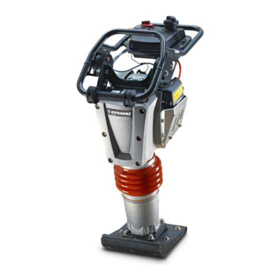
- Page 1 Operating Instruction Original Operating Instructions DFP9 Single direction vibratory plate S/N 861 924 30 1001> DL8 203 52 EN © 04/2018...
-
Page 3: Table Of Contents
3.7.1 Persons in the danger area......................30 3.7.2 Operation........................... 30 3.7.3 Parking the machine........................30 3.8 Refuelling............................. 31 3.9 Maintenance work........................32 3.9.1 Preliminary remarks........................32 3.9.2 Working on the engine....................... 32 3.9.3 Cleaning work..........................32 3.9.4 After maintenance work......................32 DFP9... - Page 4 8.3 List of fuels and lubricants......................73 8.4 Running-in instructions......................74 8.4.1 General............................74 8.4.2 After 25 operating hours......................74 8.5 Maintenance Table........................75 8.6 Weekly............................76 8.6.1 Checking, cleaning the air filter....................76 8.7 Semi-annually..........................79 8.7.1 Changing the engine oil......................79 DFP9...
- Page 5 8.9.7 Measures for longer shut-down periods..................97 Troubleshooting..........................101 9.1 Preliminary remarks........................102 9.2 Engine malfunctions......................... 103 9.3 What to do if the engine has flooded..................105 Disposal............................. 107 10.1 Final shut-down of machine....................108 List of special tools........................... 109 DFP9...
- Page 6 Table of contents DFP9...
-
Page 7: Introduction
Introduction Introduction DFP9... -
Page 8: Foreword
For your own personal safety you should only use original parts from Dynapac. For your machine we offer service kits to make maintenance easier. In the course of technical development we reserve the right for technical modifications without prior notification. - Page 9 Introduction – Foreword The above notes do not constitute an extension of the warranty and liability conditions specified in the general sales and delivery conditions of Dynapac GmbH. We wish you successful work with your Dynapac machine. DFP9...
-
Page 10: Machine Type Plate And Engine Type Plate
Serial number (2): Nominal Power Operating Mass Year of Construction Serial-No. Ammerländer Str. 93 D-26203 Wardenburg Made in Germany B-924-0001 Fig. 1: Machine type plate (example) Engine type and engine number Please enter here: Engine type: Engine number: Fig. 2 DFP9... -
Page 11: Technical Data
Technical data Technical data DFP9... - Page 12 Fig. 3 1115 (21.1) (36.0) (43.9) (22.0) (17.7) Dimensions in millimetre (Dimensions in inch) Weights Operating weight (CECE) (201) (lbs) Basic weight (198) (lbs) Water spraying system (optional equipment) (+ 15.4) (lbs) Transport wheels (optional equipment) (+ 8.8) (lbs) DFP9...
- Page 13 Exciter system Frequency (5400) (vpm) Centrifugal force (4050) (lbf) amplitude 1.63 (0.064) (in) Water sprinkling system (optional equipment) Type of sprinkling Gravity feed Filling capacities Fuel (gasoline) ( 0.8 each) (gal us) Sprinkling system (water) ( 1.9 each) (gal us) DFP9...
-
Page 14: Noise And Vibration Data
£ 2.5 m/s Total vibration value a on crushed rock determined acc. to ISO 5349 and EN 500. Associated uncertainty K = 0.3 m/s , determined acc. to EN 12096. Observe the daily vibration load (work safety acc. to 2002/44/EC). DFP9... -
Page 15: Concerning Your Safety
Concerning your safety Concerning your safety DFP9... -
Page 16: Basic Prerequisites
WARNING! Danger to life or danger of severe injuries if failing to comply! Sections marked accordingly indicate a dangerous situation that could lead to fatal or severe injuries, if this warning is disregarded. DFP9... -
Page 17: Personal Protective Equipment
Safety shoes To protect against heavy falling parts and slipping on slippery ground. Protective gloves To protect the hands against excoriation, punctures or deep injuries, against irritating and caustic substances as well as against burns. DFP9... -
Page 18: Intended Use
Dangers may arise from the machine when it is used for purposes other than the one it is intended for. Any danger caused by improper use is the sole responsibility of the operating company or driver/operator, the manufacturer cannot be made liable. DFP9... - Page 19 Starting and operating the machine in explosive environments and in underground mining is prohibited. The lifting and lashing points specified in these instructions must be used. It is prohibited to use other lifting and lashing points (e.g. guide handle, steering rod). DFP9...
-
Page 20: Definition Of Responsible Persons
Observe your local laws and regulations. Rights, obligations and rules of conduct for driver or operator: The driver or operator must: be instructed about his rights and obligations, wear protective equipment as appropriate for the application, have read and understood the operating instructions, DFP9... - Page 21 Persons under the influence of alcohol, medication or drugs are not allowed to operate, service or repair the machine. Maintenance and repair work requires specific knowledge and must therefore only be performed by trained specialists. DFP9...
-
Page 22: Basic Safety Regulations For Safe Operation
Machines which are not safe to operate or in traffic must be imme- diately taken out of service and shall not be used, until these defi- ciencies have been properly rectified. Safety installations and switches must neither be removed nor must they be made ineffective. DFP9... -
Page 23: Handling Fuels And Lubricants
/ personal protective equipment physical and chemical properties stability and reactivity toxicological data environmental data notes on waste disposal information on transport legislation other data DFP9... -
Page 24: Safety Regulations And Environmental Protection Regulations For Handling Oil
Immediately bind spilled oil with an oil-binding agent. ENVIRONMENT! Oil is an environmentally hazardous substance! – Always keep oil in proper containers. – Immediately bind spilled oil with an oil-binding agent. – Dispose of oil and oil filter according to regula- tions. DFP9... -
Page 25: Safety Regulations And Environmental Protection Regulations For Handling Gasoline
Gasoline is an environmentally hazardous sub- stance! – Always keep gasoline in proper containers. – Immediately bind spilled gasoline with an oil- binding agent and dispose of in accordance with regulations. – Dispose of gasoline and fuel filter according to regulations. DFP9... -
Page 26: Safety Regulations And Environmental Protection Regulations For Handling Fuel Stabiliser
– Avoid contact with fuel stabilizer. ENVIRONMENT! Fuel stabilizer is an environmentally hazardous substance! – Immediately bind spilled fuel stabilizer with an oil-binding agent and dispose of according to regulations. – Dispose of fuel stabilizer according to regula- tions. DFP9... -
Page 27: Loading/Transporting The Machine
Fasten the lifting gear only at the specified lifting points. Danger to the life of persons if they step or stand under a sus- pended load. When lifting the machine avoid uncontrolled movements of the load. If necessary hold the load with guide ropes. DFP9... -
Page 28: Start-Up Procedure
Always keep an eye on the machine when the engine is running and hold it by the steering bow. Do not inhale exhaust fumes, because they contain toxic sub- stances, which could cause damage to health, unconsciousness or even death. DFP9... -
Page 29: Operation In Trenches
For this reason, take care to ensure sufficient ventilation when operating the vibratory tamper or vibratory plate in more than shoulder-deep trenches which have a width of less than 1.5 metres, a maximum depth of less than 3 metres or a maximum length of less than 10 metres. DFP9... -
Page 30: Operation
Park the machine on horizontal, level, firm ground. Before leaving the machine: Shut down the engine, Secure the machine against accidental tipping over, Secure the machine against unauthorized use. Mark machines, which could be in the way, with a clearly visible sign. DFP9... -
Page 31: Refuelling
Do not spill any fuel. Catch running out fuel, do not let it seep into the ground. Wipe off spilled fuel. Keep dirt and water away from the fuel. A leaking fuel tank can cause an explosion. Ensure tight fit of the fuel tank cover, if necessary replace immediately. DFP9... -
Page 32: Maintenance Work
Do not perform cleaning work while the motor is running. Allow the engine to cool down before starting cleaning work. Do not use gasoline or other easily inflammable substances for cleaning. 3.9.4 After maintenance work Reassemble all guards and protections. DFP9... -
Page 33: Repair
Only operate the machine after it has been repaired. When replacing safety relevant components, only original spare parts must be used. Repairs must only be performed by an expert/qualified person. When performing welding work on the machine you should cover the fuel tank with insulating material. DFP9... -
Page 34: Signage
Inbetriebnahme wöchentlich avant la mise en service hebdomadairement anterior a la puesta en servicio cada semana annual twice annual jährlich halbjährlich tous les 6 mois annuellement cada 6 meses anualmente 008 338 01 B-924-0015 Fig. 6 DFP9... - Page 35 Concerning your safety – Signage Warning sticker - Follow operating instructions Fig. 7 Instruction sticker - Wear ear defenders Fig. 8 Information sticker - Guaranteed sound capacity level Fig. 9 Information sticker - Lashing point Fig. 10 DFP9...
- Page 36 Concerning your safety – Signage Information sticker - Lifting point Fig. 11 Information sticker - Filler opening for petrol Gasoline/Benzin B-DEC-0216 Fig. 12 Information sticker - Filler opening for water Water B-DEC-0218 Fig. 13 Brief operating instructions Fig. 14 DFP9...
- Page 37 6 mois cada 6 meses anualmente B-DEC-0276 Fig. 15 Machine type plate (example) Made by Designation Type Nominal Power Operating Mass Year of Construction Serial-No. Ammerländer Str. 93 D-26203 Wardenburg Made in Germany B-924-0002 Fig. 16 DFP9...
- Page 38 Concerning your safety – Signage DFP9...
-
Page 39: Indicators And Control Elements
Indicators and control elements Indicators and control elements DFP9... -
Page 40: Engine
Indicators and control elements – Engine 4.1 Engine 4.1.1 Overview Fig. 17 Start switch Throttle lever Choke lever Recoil starter Fuel valve 4.1.2 Starter switch Position “OFF” Ignition off Position “ON” Ignition on Fig. 18 DFP9... -
Page 41: Throttle Lever
Indicators and control elements – Engine 4.1.3 Throttle lever Position "MIN" Idle speed Position "MAX" Maximum speed Fig. 19 4.1.4 Choke lever Position "Left" Choke closed Position "Right" Choke open Fig. 20 4.1.5 Recoil starter Fig. 21 DFP9... -
Page 42: Fuel Valve
Indicators and control elements – Engine 4.1.6 Fuel valve Position "Left" Fuel valve closed Position "Right" Fuel valve open Fig. 22 DFP9... -
Page 43: Water Spraying System
4.2 Water spraying system Shut-off valve for water spraying system Fig. 23 4.2.1 Shut-off valve Position “0” Water spraying system off turn anticlockwise Water spraying system on infinite adjustment of the spraying quan- tity up to “MAX” position Fig. 24 DFP9... -
Page 44: Transport Wheels
Indicators and control elements – Transport wheels 4.3 Transport wheels Fig. 25 Locking of guide handle Locking of transport wheels DFP9... -
Page 45: Checks Prior To Start Up
Checks prior to start up Checks prior to start up DFP9... -
Page 46: Notes On Safety
Danger of injury caused by rotating parts! – Before starting work on the machine make sure that the engine can not be started. Park the machine safely Ä Chapter 6.5 „Parking the machine in secured condition“ on page 62. DFP9... -
Page 47: Visual Inspections And Function Tests
5.2 Visual inspections and function tests Check fuel tank and lines for condition and leaks. Check bolted connections for tight fit. Check machine for contamination and damage. Check the hydraulic oil cooler for dirt. Check starter rope for chafing. DFP9... -
Page 48: Checking The Engine Oil Level
ð The oil level must be between the “MIN” and “MAX” marks. NOTICE! B-834-0026 Danger of engine damage! Fig. 27 – Do not fill in too much engine oil. If the oil level is too low, top up oil to the “MAX” mark. Screw the oil dipstick in. DFP9... -
Page 49: Checking The Fuel Level; Topping Up Fuel
Park the machine safely in secured condition“ on page 62. Clean the area around the filling port. Remove the cap and check the filling level visually. If necessary, fill in fuel through a funnel with screen filter. Close the cap. Fig. 29 DFP9... -
Page 50: Checking The Rubber Buffers
5.5 Checking the rubber buffers B-SYM-1073 Fig. 30 Protective equipment: Working clothes Safety shoes Protective gloves Check the rubber buffer pairs, left and right, for tight fit, cracks and tear-offs. ð Replace damaged rubber buffers immediately. B-834-0081 Fig. 31 DFP9... -
Page 51: Checking The Water Level, Topping Up
Fig. 32 Alternatively, the water tank can also be removed and transported for filling. Close the shut-off valve (1). Loosen the hose clamp and pull the hose (2) off the shut-off valve. Lift off the water tank upwards. Fig. 33 DFP9... - Page 52 Checks prior to start up – Checking the water level, topping up DFP9...
-
Page 53: Operation
Operation Operation DFP9... -
Page 54: Mounting The Guide Handle
Fig. 34 Force the guide handle apart and plug it onto the holding fix- tures. Lock and secure the guide handle on both sides with split pins. Fig. 35 DFP9... -
Page 55: Starting The Engine
Protective equipment: Hearing protection Working clothes Protective gloves Safety shoes The engine does not start if the oil level is too low. Fold down the guide handle into working position. Make sure that no persons are in the danger zone. DFP9... - Page 56 If the engine is warm or the outside tempera- tures are high, the choke must remain open to prevent the engine from stalling. Close the choke. Fig. 37 Set the throttle lever to “MIN” position. Fig. 38 Turn the starter switch to “ON” position. Fig. 39 DFP9...
- Page 57 Warm up engine for a short while before starting work. Do not operate the engine immediately under full load. Fig. 42 If the engine stops again after approx. 3 to 5 seconds: Close the choke again. Repeat the starting procedure. DFP9...
- Page 58 Operation – Starting the engine If the recoil starter is frequently operated with the choke closed, the engine will draw in too much fuel and is unable to start Ä Chapter 9.3 „What to do if the engine has flooded“ on page 105. DFP9...
-
Page 59: Operation
Make sure that no persons are in the danger zone. NOTICE! The centrifugal clutch may be damaged! – Operate the machine only with the throttle lever in “MAX” position. Set the throttle lever to “MAX” position. ð Machine vibrates forward. Fig. 43 DFP9... - Page 60 Operation – Operation Guide the machine by means of the guide handle. Fig. 44 For short work interruptions you should always return the throttle lever to “MIN” position (idle speed). ð Vibration is switched off. Fig. 45 DFP9...
-
Page 61: Switching The Water Spraying System On/Off
6.4 Switching the water spraying system on/off The water spraying system must be switched on and off by the shut-off valve: Position “0” Water spraying system off turn anticlockwise Water spraying system on infinite adjustment of the spraying quantity up to “MAX” position Fig. 46 DFP9... -
Page 62: Parking The Machine In Secured Condition
Danger of engine damage! – Do not shut down the engine all of a sudden from full load speed, but let it idle for about two minutes. Turn the starter switch to “OFF” position. ð The engine is shut down. Fig. 48 DFP9... - Page 63 Operation – Parking the machine in secured condition Close the fuel valve completely. secure the machine against unauthorized use. Fig. 49 DFP9...
- Page 64 Operation – Parking the machine in secured condition DFP9...
-
Page 65: Loading/Transporting The Machine
Loading/transporting the machine Loading/transporting the machine DFP9... -
Page 66: Loading The Machine
– Do not step or stand under suspended loads. Lift the machine carefully and lower it again at the intended location. Fig. 50 If necessary, pull the machine by the handles on an even sur- face. Fig. 51 DFP9... -
Page 67: Lashing The Machine To The Transport Vehicle
Fold down the guide handle. Pull at least two suitable lashing belts crosswise across the marked lashing point. Lash the machine securely to the transport vehicle as shown. Use suitable gear to prevent the guide handle from swinging over unintentionally. Fig. 52 DFP9... -
Page 68: Transport Wheels
Unlock the locking bolt (2) and fold down the transport wheels. B-834-0225 Fig. 53 Push the machine up by the guide handle and fold the trans- port wheels under the base plate. ð The machine can now be moved. B-834-0226 Fig. 54 DFP9... -
Page 69: Maintenance
Maintenance Maintenance DFP9... -
Page 70: Preliminary Remarks And Safety Notes
After maintenance work has been completed, dispose of fuels and lubricants, filters, sealing elements and cleaning cloths in an envi- ronmentally friendly way. After all maintenance work is completed reinstall all guards and safety installations. DFP9... -
Page 71: Fuels And Lubricants
Methanol must also contain co-solvents and corrosion inhibitors. Do not use any fuel with a higher ethanol or methanol content. The use of fuels with a higher ethanol or methanol content will cause starting and/or power problems or even cause damage in the fuel system. DFP9... -
Page 72: Oil For Exciter Shaft Housing
8.2.3 Oil for exciter shaft housing Use only engine oils according to the following specifications: API CI-4 or higher quality Avoid mixing engine oils. NOTICE! Components may get damaged! – Do not use low-ash engine oils for the exciter shaft housing. DFP9... -
Page 73: List Of Fuels And Lubricants
Ä Chapter 8.2.3 „Oil for exciter Specification: (0.07 gal us) shaft housing“ on page 72 Components may get damaged! Do not use low-ash engine oils for the exciter shaft housing. SAE 15W-40 SAE 10W-30 Water tank Water Anti-freeze mixture 7.0 l (1.8 gal us) DFP9... -
Page 74: Running-In Instructions
Retighten the fastening screws on air filter, exhaust and other attachments. Retighten the bolted connections on the machine. Ä Chapter 8.9.4 „Servicing the V- Checking the V-belt belt“ on page 94. Check the oil level in the vibrator housing. DFP9... -
Page 75: Maintenance Table
Cleaning the cooling fins and the cooling air intake openings 8.9.2 Cleaning the machine 8.9.3 Cleaning the water spraying system 8.9.4 Servicing the V-belt 8.9.5 Checking, cleaning the spark plug 8.9.6 Measures if there is a risk of frost 8.9.7 Measures for longer shut-down periods DFP9... -
Page 76: Weekly
Unscrew wing nut (1) and remove cover (2). Clean the cover. Unscrew wing nut (3) and remove filter element (4). Check the rubber seal (5), replace if necessary. The rubber seal frequently sticks to the filter element. B-HON-0033 Fig. 57 DFP9... - Page 77 Clean the foam element (5) in warm soapy water, rinse it and let it dry thoroughly. Soak the foam element in clean engine oil and press exces- sive oil out. Check both elements thoroughly for holes and cracks. Replace if damaged. Pull the foam rubber element over the paper element. DFP9...
- Page 78 Insert the filter element (4) correctly and tighten it with the wing nut (3). Tighten the cover (2) with the wing nut (1). Dispose of the filter element (if replaced) in an environmen- tally friendly way. B-HON-0033 Fig. 60 DFP9...
-
Page 79: Semi-Annually
Fill in fresh oil up to the bottom edge of the filler bore. Push the oil dipstick (1) back in. Check for leaks after a short test run. Check the oil level on the dipstick, correct if necessary. Dispose of oil in line with environmental regulations. B-834-0026 Fig. 63 DFP9... -
Page 80: Annually
Perform this maintenance work at the latest after 250 operating hours NOTICE! Danger of engine damage! We recommend to have this work carried out by trained personnel or our after sales service. – Before checking the valve clearance let the engine cool down. DFP9... - Page 81 Valve clearance: Intake valve (IN) 0.08 mm (0.003 in) Exhaust valve (EX) 0.10 mm (0.004 in) Check the valve clearance with a feeler gauge between rocker arm (2) and valve shaft (1) on both valves, adjust if necessary. Fig. 67 DFP9...
-
Page 82: Replacing The V-Belt
Safety shoes Protective gloves Park the machine safely Ä Chapter 6.5 „Parking the machine in secured condition“ on page 62. Allow the engine to cool down. Loosen the fastening screws (2) and remove the V-belt guard (1). B-834-0144 Fig. 70 DFP9... - Page 83 Assemble the V-belt guard (1) with fastening screws (2). Check the V-belt tension again after 25 operating hours, tighten if necessary. B-834-0144 Fig. 74 8.8.3.1 Checking the frequency of the base plate Keep feet and hands clear of the vibrating base plate. DFP9...
-
Page 84: Cleaning The Slurry Filter And Fuel Strainer
– Do not spill any gasoline. Protective equipment: Working clothes Protective gloves Ä Chapter 6.5 Park the machine in secured condition „Parking the machine in secured condition“ on page 62. Allow the engine to cool down. DFP9... - Page 85 Clean filter bowl and filter in a non-inflammable solvent, dry them thoroughly afterwards. Fig. 76 A View from below: Alignment of filter during installation Open the fuel valve and collect running out fuel. Close the fuel valve. Fig. 77 DFP9...
- Page 86 Assemble the fuel hose with the hose clamp. Fig. 80 Assemble the fuel tank with hexagon nuts (2) and hexagon screw (1). Check the fuel system for leaks. Dispose of fuel and replaced components in an environmen- tally friendly way. Fig. 81 DFP9...
-
Page 87: Replacing The Air Filter
Unscrew wing nut (3) and remove filter element (4). Check the rubber seal (5), replace if necessary. The rubber seal frequently sticks to the filter element. Fig. 82 Replace the filter element consisting of paper and foam insert. Fig. 83 DFP9... -
Page 88: Replacing The Starter Rope
8.8.6 Replacing the starter rope Protective equipment: Working clothes Protective gloves Ä Chapter 6.5 Park the machine in secured condition „Parking the machine in secured condition“ on page 62. Allow the engine to cool down. Disassembling the recoil starter. Fig. 85 DFP9... - Page 89 Do not let the starter handle hit back. Remove the fixing of the coil and run the starter handle slowly back to initial position. Pull the starter handle to check the function and light move- ment of the recoil starter. Fig. 89 DFP9...
-
Page 90: Changing The Oil In The Exciter Housing
Park the machine in secured condition „Parking the machine in secured condition“ on page 62. Tilt the machine slightly towards the oil drain side and sup- port it safely. Unscrew the oil drain plug (1) and collect running out oil. Fig. 91 DFP9... - Page 91 Do not use low-ash engine oils for the exciter shaft housing. Fill in oil up to the bottom edge of the bore. Screw in the oil drain plug (1). Fig. 92 Dispose of oil in an environmentally friendly way. DFP9...
-
Page 92: As Required
Wear your personal protective equipment (safety gloves, protective working clothes, goggles). Fig. 93 Blow out the cooling fins and cooling air intake openings with compressed air. Cleaning with cold cleansing agent If the engine is oily, use a cold cleansing agent for cleaning. DFP9... -
Page 93: Cleaning The Machine
– Do not direct the water jet directly into the air filter, carburettor, recoil starter, air intake or starter switch. Clean the machine with a water jet. Run the engine warm for a while to avoid corrosion. DFP9... -
Page 94: Cleaning The Water Spraying System
Check condition and tension of the V-belt, tighten if neces- sary. ð Compression measurement: approx. 5 mm (0.2 in). If necessary, tighten the V-belt; if damaged, replace the V- belt Ä Chapter 8.8.3 „Replacing the V-belt“ on page 82. Fig. 96 DFP9... -
Page 95: Checking, Cleaning The Spark Plug
„Parking the machine in secured condition“ on page 62. Allow the engine to cool down for at least 15 minutes. Clean the area around the spark plug. Unscrew the spark plug using a 13/16 inch spark plug spanner. Fig. 98 DFP9... -
Page 96: Measures If There Is A Risk Of Frost
Remove the cap (1) from the water tank. Remove the rubber caps (3) from the spray tube. Open shut-off valve (2) and drain off all water. Insert the rubber caps. Close the shut-off valve. Close the cap. Fig. 100 DFP9... -
Page 97: Measures For Longer Shut-Down Periods
Empty the fuel tank and fill it with the prepared fuel mix. Start the engine and run the machine for approx. 10 minutes in the open. Park the machine in secured condition. Emptying the fuel tank. Close the fuel valve. Fig. 101 DFP9... - Page 98 After shutting down store the machine under cover in a dry and well ventilated room. Cover the engine to protect it against dust and moisture. A machine with conserved engine must be clearly marked by attaching an information sign. DFP9...
- Page 99 If the fuel was drained off before shutting down, you must now fill in fuel. Check hoses and lines for cracks and leaks. Clean the machine thoroughly. Start the engine and run it for 15 to 30 minutes with idle speed. DFP9...
- Page 100 Maintenance – As required DFP9...
-
Page 101: Troubleshooting
Troubleshooting Troubleshooting DFP9... -
Page 102: Preliminary Remarks
Whenever a fault occurs you should therefore thoroughly read these instructions on correct operation and maintenance. If you cannot locate the cause of a fault or rectify it yourself by fol- lowing the trouble shooting chart, you should contact our customer service department. DFP9... -
Page 103: Engine Malfunctions
Cleaning the cooling fins and the cooling air intake openings Engine stops Fuel system clogged Clean the fuel screen Check the fuel screen in the carburettor Have checked by qualified expert per- sonnel Fuel tank empty Check, fill up if necessary DFP9... - Page 104 Engine oil level too low Check the engine oil level, correct if nec- essary Engine runs with Centrifugal clutch defective Have checked by qualified expert per- high speed, but no sonnel vibration V-belt broken Replacing the V-belt DFP9...
-
Page 105: What To Do If The Engine Has Flooded
Allow the engine to cool down. Close the fuel valve. Fig. 105 Pull off the spark plug socket. Unscrew the spark plug using a 13/16 inch spark plug spanner. Have a cloth ready to soak up the fuel. Fig. 106 DFP9... - Page 106 Always screw the spark plug in correctly. Plug the spark plug socket back on. Ä Chapter 6.2 „Starting the Start the engine engine“ on page 55. Dispose of the cloth soaked with the leaked fuel in an envi- ronmentally friendly way. DFP9...
-
Page 107: Disposal
Disposal Disposal DFP9... -
Page 108: Final Shut-Down Of Machine
Ä Chapter 3.4 „Han- dling fuels and lubricants“ on page 23. Protective equipment: Working clothes Safety shoes Protective gloves Safety goggles Empty the fuel tank. Drain engine oil from engine and exciter housing. DFP9... -
Page 109: List Of Special Tools
List of special tools List of special tools DFP9... - Page 110 List of special tools 13/16 inch spark plug spanner Fig. Sirometer Measuring instrument for speed and frequency Fig. DFP9...
Need help?
Do you have a question about the DFP9 and is the answer not in the manual?
Questions and answers