Table of Contents
Advertisement
Quick Links
Advertisement
Table of Contents
Troubleshooting

Related Manuals for Miller Big 40 C


Summary of Contents for Miller Big 40 C
- Page 1 215 622AA 2010−06 Processes Stick (SMAW) Welding TIG (GTAW) Welding MIG (GMAW) Welding Flux Cored (FCAW) Welding Air Carbon Arc (CAC-A) Cutting and Gouging Description Engine Driven Welding Generator Big 40 C File: Engine Drive Visit our website at www.MillerWelds.com...
- Page 2 We know you don’t have time to do it any other way. That’s why when Niels Miller first started building arc welders in 1929, he made sure his products offered long-lasting value and superior quality.
-
Page 3: Table Of Contents
TABLE OF CONTENTS SECTION 1 − SAFETY PRECAUTIONS − READ BEFORE USING ........1-1. - Page 4 TABLE OF CONTENTS SECTION 7 − OPERATING WELDING GENERATOR − CC/CV MODELS ......7-1.
-
Page 5: Section 1 − Safety Precautions − Read Before Using
SECTION 1 − SAFETY PRECAUTIONS − READ BEFORE USING rom_2010−03 Protect yourself and others from injury — read, follow, and save these important safety precautions and operating instructions. 1-1. Symbol Usage DANGER! − Indicates a hazardous situation which, if Indicates special instructions. not avoided, will result in death or serious injury. - Page 6 D Do not weld on closed containers such as tanks, drums, or pipes, FUMES AND GASES can be hazardous. unless they are properly prepared according to AWS F4.1 (see Safety Standards). Welding produces fumes and gases. Breathing these D Do not weld where the atmosphere may contain flammable dust, fumes and gases can be hazardous to your health.
-
Page 7: Engine Hazards
1-3. Engine Hazards EXHAUST SPARKS can cause fire. BATTERY EXPLOSION can injure. D Do not let engine exhaust sparks cause fire. D Always wear a face shield, rubber gloves, and protective clothing when working on a battery. D Use approved engine exhaust spark arrestor in required areas —... -
Page 8: Hydraulic Hazards
1-4. Hydraulic Hazards D HYDRAULIC FLUID is FLAMMABLE−−do not work on hydraulics HYDRAULIC EQUIPMENT can injure near sparks or flames; do not smoke near hydraulic fluid. or kill. D Reinstall doors, panels, covers, or guards when servicing is D Incorrect installation or operation of this unit finished and before starting unit. -
Page 9: Additional Symbols For Installation, Operation, And Maintenance
HOT METAL from air arc cutting and MOVING PARTS can injure. gouging can cause fire or explosion. D Keep away from moving parts such as fans, D Do not cut or gouge near flammables. belts and rotors. D Watch for fire; keep extinguisher nearby. D Keep all doors, panels, covers, and guards closed and securely in place. -
Page 10: California Proposition 65 Warnings
WELDING WIRE can injure. H.F. RADIATION can cause interference. D Do not press gun trigger until instructed to do D High-frequency (H.F.) can interfere with radio navigation, safety services, computers, and communications equipment. D Do not point gun toward any part of the body, other people, or any metal when threading D Have only qualified persons familiar with welding wire. -
Page 11: Principal Safety Standards
1-8. Principal Safety Standards Safety in Welding, Cutting, and Allied Processes, ANSI Standard Z49.1, 25 West 43rd Street, New York, NY 10036 (phone: 212-642-4900, web- from Global Engineering Documents (phone: 1-877-413-5184, website: site: www.ansi.org). www.global.ihs.com). Standard for Fire Prevention During Welding, Cutting, and Other Hot Safe Practices for the Preparation of Containers and Piping for Welding Work, NFPA Standard 51B, from National Fire Protection Association, and Cutting, American Welding Society Standard AWS F4.1, from Glob-... -
Page 12: Section 2 − Consignes De Sécurité − Lire Avant Utilisation
SECTION 2 CONSIGNES DE SÉCURITÉ − LIRE AVANT − UTILISATION fre_rom_2010−03 Pour écarter les risques de blessure pour vous−même et pour autrui — lire, appliquer et ranger en lieu sûr ces consignes relatives aux précautions de sécurité et au mode opératoire. 2-1. - Page 13 D Porter un casque de soudage approuvé muni de verres filtrants LES PIÈCES CHAUDES peuvent approprié pour protéger visage et yeux pour protéger votre visage provoquer des brûlures. et vos yeux pendant le soudage ou pour regarder (voir ANSI Z49.1 et Z87.1 énuméré...
-
Page 14: Dangers Existant En Relation Avec Le Moteur
D Placer les bouteilles debout en les fixant dans un support station- Les CHAMPS ÉLECTROMAGNÉTIQUES (CEM) naire ou dans un porte-bouteilles pour les empêcher de tomber ou peuvent affecter les implants médicaux. de se renverser. D Tenir les bouteilles éloignées des circuits de soudage ou autres D Les porteurs de stimulateurs cardiaques et circuits électriques. -
Page 15: Dangers Liés À L'hydraulique
D Mettre des lunettes de sécurité et des gants, placer un torchon sur LES ÉTINCELLES À L’ÉCHAPPEMENT le bouchon du radiateur. peuvent provoquer un incendie. D Dévisser le bouchon légèrement et laisser la vapeur s’échapper avant d’enlever le bouchon. D Empêcher les étincelles d’échappement du moteur de provoquer un incendie. -
Page 16: Dangers Liés À L'air Comprimé
un médecin familiarisé avec ce type de blessure, faute de quoi LES PIÈCES ET LIQUIDES CHAUDS la gangrène pourrait apparaître. peuvent provoquer des brûlures. Les PIÈCES MOBILES peuvent causer D Ne pas toucher les pièces chaudes à main nue des blessures. ni laisser des liquides chauds entrer en contact avec la peau. -
Page 17: Dangers Supplémentaires En Relation Avec L'installation, Le Fonctionnement Et La Maintenance
D Remettre en place les portes, panneaux, recouvrements ou PRESSION D’AIR RÉSIDUELLE dispositifs de protection à la fin des travaux d’entretien et avant ET DES FLEXIBLES QUI FOUETTENT de mettre le moteur en marche. risquent de provoquer des blessures. D Détendre la pression pneumatique des outils et PIÈCES CHAUDES peuvent... -
Page 18: Proposition Californienne 65 Avertissements
D Demander seulement à des personnes qualifiées familiarisées LES CHARGES ÉLECTROSTATI- avec des équipements électroniques de faire fonctionner l’installa- QUES peuvent endommager les tion. circuits imprimés. D L’utilisateur est tenu de faire corriger rapidement par un électricien qualifié les interférences résultant de l’installation. D Établir la connexion avec la barrette de terre avant de manipuler des cartes ou des pièces. -
Page 19: Principales Normes De Sécurité
2-8. Principales normes de sécurité Safety in Welding, Cutting, and Allied Processes, ANSI Standard Z49.1, 25 West 43rd Street, New York, NY 10036 (phone: 212-642-4900, web- from Global Engineering Documents (phone: 1-877-413-5184, website: site: www.ansi.org). www.global.ihs.com). Standard for Fire Prevention During Welding, Cutting, and Other Hot Safe Practices for the Preparation of Containers and Piping for Welding Work, NFPA Standard 51B, from National Fire Protection Association, and Cutting, American Welding Society Standard AWS F4.1, from Glob-... -
Page 20: Section 3 − Definitions
SECTION 3 − DEFINITIONS 3-1. Warning Label Definitions (For Wordless Labels) Remove unit from shipping S-177 571 crate. Remove Owner’s Manual from unit. Follow instructions to install muffler. Read Owner’s Manual. Read labels on unit. Use Diesel Fuel only, and fill fuel tank. -
Page 21: Symbols And Definitions
3-2. Symbols And Definitions Some symbols are found only on export products. Fast (Run, Weld/ Stop Engine Slow (Idle) Start Engine Power) Engine Oil Starting Aid Battery (Engine) Engine Oil Pressure Check Injectors/ Check Valve Protective Earth Fuel Pump Clearance (Ground) Certified/Trained Positive... -
Page 22: Section 4 − Specifications
SECTION 4 − SPECIFICATIONS 4-1. Weld, Power, And Engine Specifications Maximum Welding Weld Output Rated Welding Open- Generator Power Fuel Engine Mode Range Output Circuit Rating Capacity Voltage Export Models: 300 A, 32 Volts DC, 100% Duty Cycle 55 − 500 A 430 A, 37 Volts DC, (CC Models) Standard... -
Page 23: Volt-Ampere Curves For Cc Models
4-3. Volt-Ampere Curves For CC Models The volt-ampere curve shows the minimum and maximum voltage and amperage output capabilities of the welding generator. Curves of all other settings fall between the curves shown. Ranges: 230 − Max 170 − 365 110 −... -
Page 24: Volt-Ampere Curves For Cc/Cv Models
4-4. Volt-Ampere Curves For CC/CV Models A. Stick Mode The volt-ampere curves show the minimum and maximum voltage and amperage output capabilities of the welding generator. Curves of all RANGES: other settings fall between the curves shown. 155 − 450 115 −... -
Page 25: Fuel Consumption
4-5. Fuel Consumption The curve shows typical fuel use under weld or power loads. 2.50 2.25 2.00 1.75 1.50 1.25 1.00 0.75 0.50 IDLE 0.25 0.00 DC WELD AMPERES AT 100% DUTY CYCLE 199 032−A 4-6. Duty Cycle And Overheating Duty Cycle is percentage of 10 min- 100% Duty Cycle At 400 Amperes utes that unit can weld at rated load... -
Page 26: Ac Generator Power Curve
4-7. AC Generator Power Curve The AC power curve shows the generator power in amperes avail- able at the 120 and 240 volt receptacles. AC AMPERES IN 240V MODE AC AMPERES IN 120V MODE 193 018 4-8. Optional Three-Phase Generator Curves The AC power curves show the A. -
Page 27: Section 5 − Installation
SECTION 5 − INSTALLATION 5-1. Serial Number And Rating Label Location The serial number and rating information for this product is located on the front. Use rating label to determine input power requirements and/or rated output. For future reference, write serial number in space provided on back cover of this manual. 5-2. -
Page 28: Mounting Welding Generator
5-3. Mounting Welding Generator Do not weld on base. Weld- ing on base can cause fuel tank fire or explosion. Weld only on the four mounting brackets or bolt unit down. Supporting The Unit NOTICE − Do not mount unit by supporting the base only at the four mounting brackets. -
Page 29: Grounding Generator To Truck Or Trailer Frame
5-4. Grounding Generator To Truck Or Trailer Frame Always ground generator frame to vehicle frame to pre- vent electric shock and static electricity hazards. Also see AWS Safety & Health Fact Sheet No. 29, Grounding of Portable And Vehicle Mounted Welding Generators. -
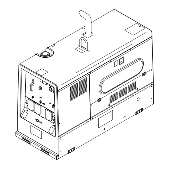
Page 30: Installing Exhaust Pipe
5-6. Installing Exhaust Pipe Stop engine and let cool. Point exhaust pipe in desired di- rection but always away from front panel and direction of travel. Tools Needed: 1/2 in. Exhaust1 2008−01 Ref. 803 604 / Ref. 236 972 Notes OM-4427 Page 26... -
Page 31: Activating The Dry Charge Battery (If Applicable)
5-7. Activating The Dry Charge Battery (If Applicable) Always wear a face shield, rubber gloves and protective clothing when working on a battery. Remove battery from unit. Vent Caps Sulfuric Acid Electrolyte (1.265 Specific Gravity) Well Fill each cell with electrolyte to bottom of well (maximum). -
Page 32: Engine Prestart Checks
5-9. Engine Prestart Checks Check radiator coolant level when fluid is low in recovery tank. Full Capacity: 404.22 Engine: 9.5 qt (9.01L) Full Diesel Full Coolant Recovery Tank Hot Full Cold Full 803 603 Engine stops if fuel level is low. freeze to mixture if using the unit in tempera- Check all engine fluids daily. -
Page 33: Connecting To Weld Output Terminals
5-10. Connecting To Weld Output Terminals Stick and TIG Welding MIG and FCAW Welding For Stick and TIG welding Direct Current Elec- For MIG and FCAW welding Direct Current trode Positive (DCEP), connect electrode Electrode Positive (DCEP) on CC/CV models, holder cable to Positive (+) terminal on left and connect wire feeder cable to Positive (+) termi- work cable to Negative (−) terminal on right. -
Page 34: Selecting Weld Cable Sizes
( ) = mm for metric use ***For distances longer than those shown in this guide, call a factory applications rep. at 920-735-4505 (Miller) or 1-800-332-3281 (Hobart) Ref. S-0007-G 2009−08 5-12. Connecting To Remote Amperage Adjust Receptacle RC13 On CC Models... -
Page 35: Connecting To Remote 14 Receptacle Rc14 On Cc/Cv Models
5-13. Connecting To Remote 14 Receptacle RC14 On CC/CV Models Socket* Socket Information 24 volts AC. Protected by sup- plementary protector CB5. 24 VOLTS AC Contact closure to A completes 24 volt AC contactor control circuit. Output to remote control:+10 volts DC in MIG or Stick mode;... -
Page 36: Section 6 − Operating Welding Generator − Cc Models
SECTION 6 − OPERATING WELDING GENERATOR − CC MODELS 6-1. Front Panel Controls For CC Models (See Section 6-2) 236 970 / 803 602 OM-4427 Page 32... -
Page 37: Description Of Front Panel Controls For Cc Models (See Section 6-1)
6-2. Description Of Front Panel Controls For CC Models (See Section 6-1) Engine Starting Controls (69 kPa). When switch is in the Stick position, the max OCV circuit resets Amperage Adjust Control Engine Coolant Temperature Gauge Starting Aid Switch R1 to maximum when the arc breaks. (Optional) Use switch to energize starting aid for cold Also in the Stick position, the arc drive (dig) -
Page 38: Remote Amperage Control On Cc Models (Optional)
6-3. Remote Amperage Control On CC Models (Optional) Remote Amperage Adjust Receptacle RC13 Connect optional remote control to RC13 (see Section 5-12). In Example: Example: Combination Remote Amperage Control (Stick) Range = 110 to 225 A DC Percentage Of Range = 50% Max = About 168 A DC (50% of 110 to 225) Max (168 A DC) Min (90 A DC) - Page 39 Notes OM-4427 Page 35...
-
Page 40: Section 7 − Operating Welding Generator − Cc/Cv Models
SECTION 7 − OPERATING WELDING GENERATOR − CC/CV MODELS 7-1. Front Panel Controls For CC/CV Models (See Section 7-2) 236 971 / 803 602 OM-4427 Page 36... -
Page 41: Description Of Front Panel Controls For Cc/Cv Models (See Section 7-1)
7-2. Description Of Front Panel Controls For CC/CV Models (See Section 7-1) Engine Starting Controls Engine Coolant Temperature Gauge Use switch to select front panel or remote (Optional) voltage/amperage control. For remote con- Starting Aid Switch trol, place switch in Remote position and con- Normal temperature is 180 - 203°... -
Page 42: Process/Contactor Switch On Cc/Cv Models
7-3. Process/Contactor Switch On CC/CV Models Process/Contactor Switch Weld output terminals are ener- gized when Process/Contactor switch is in an Weld Terminals Always On position and the en- gine is running. DC voltage is still present at the weld terminals when Process/ Contactor switch is in the Re- mote On/Off Switch Required −... -
Page 43: Remote Voltage/Amperage Control On Cc/Cv Models (Optional)
7-4. Remote Voltage/Amperage Control On CC/CV Models (Optional) Remote 14 Receptacle RC14 Connect optional remote control to RC14 (see Section 5-13). In Example: Example: Combination Remote Amperage Control (Stick) Process = Stick (Using Remote On/Off) Range = 115 to 320 A DC Min = 115 A DC Max = 320 A DC Max (320 A DC) -
Page 44: Fuel/Hour Gauge Descriptions
7-5. Fuel/Hour Gauge Descriptions OM-4427 Page 40... -
Page 45: Section 8 − Operating Auxiliary Equipment
SECTION 8 − OPERATING AUXILIARY EQUIPMENT 8-1. Domestic Auxiliary Power Receptacles 120 V 20 A AC GFCI Receptacle GFCI1 240 V 30 A AC Twistlock Receptacle RC1 Receptacles supply 60 Hz single- phase power at weld/power speed. If a ground fault is detected, GFCI Reset button pops... -
Page 46: Connecting To Optional Three-Phase Generator (Cc/Cv Models Only)
8-2. Connecting To Optional Three-Phase Generator (CC/CV Models Only) Place Process/Contactor switch in Weld Terminals Always On - Stick position when using three- phase generator (see Section Single-Phase Power Connection 7-3). Single-Phase Generator Power 120/240 V 50 A Receptacle RC5 is connected to the optional three-phase generator and supplies 60 Hz single-phase power at weld/ power speed. -
Page 47: Export Auxiliary Power Receptacles
8-3. Export Auxiliary Power Receptacles European Receptacle Australian Receptacle South African Receptacle 238 127-A / 805 259-A 120V 15/20A AC Receptacle GFCI1 tacles is 4 kVA/kW. does not work. Place circuit breaker switch in the On position to reset breaker. Receptacles supply 60 Hz single-phase EXAMPLE: If 13 A is drawn from RC1, only power at weld/power speed. -
Page 48: Section 9 − Maintenance & Troubleshooting
SECTION 9 − MAINTENANCE & TROUBLESHOOTING 9-1. Maintenance Label OM-4427 Page 44... -
Page 49: Routine Maintenance
9-2. Routine Maintenance Stop engine before maintaining. See Engine Manual and Maintenance Label Recycle engine for important start-up, service, and storage fluids. information. Service engine more often if used in severe conditions. n = Check Z = Change ~ = Clean l = Replace Reference * To be done by Factory Authorized Service Agent... -
Page 50: Checking Generator Brushes
9-3. Checking Generator Brushes Stop engine and let cool. Generator Brush Mark and disconnect leads at brush hold- er cap. Remove brushes. Replace brushes if damaged or if brush material is at or near minimum length. Minimum Length: 5/8 in. (16 mm) New Length: 1-1/4 in. -
Page 51: Servicing Air Cleaner
9-4. Servicing Air Cleaner Stop engine. NOTICE − Do not run engine without air cleaner or with dirty element. Engine damage caused by using a damaged ele- ment is not covered by the warranty. The air cleaner primary element can be cleaned but the dirt holding capac- ity of the filter is reduced with each cleaning. -
Page 52: Inspecting And Cleaning Optional Spark Arrestor Muffler
9-5. Inspecting And Cleaning Optional Spark Arrestor Muffler Stop engine and let cool. Spark Arrestor Muffler Cleanout Plug Remove plug and remove any dirt covering cleanout hole. Start engine and run at idle speed to blow out cleanout hole. If nothing blows out of hole, briefly cover end of exhaust pipe with fireproof material. -
Page 53: Adjusting Engine Speed
9-6. Adjusting Engine Speed Engine Speed Adjustment Engine Speed After tuning engine, check en- (No Load) gine speed with tachometer or frequency meter. See table for 1850 rpm max proper no load speed. If neces- (61.6 Hz) sary, adjust speed as follows: 1250 rpm Start engine and run until warm. -
Page 54: Servicing Fuel And Lubrication Systems
9-7. Servicing Fuel And Lubrication Systems Stop engine and let cool. After servicing, start engine and check for fuel leaks. Stop engine, tighten connec- tions as necessary, and wipe up spilled fuel. Oil Filter Oil Drain Valve And Hose Oil Fill Cap Fuel Line Primary Fuel Filter (Fuel/ Water Separator) -
Page 55: Overload Protection
9-8. Overload Protection Stop engine. When a supplementary protector, circuit breaker or fuse opens, it usu- ally indicates a more serious problem exists. Contact Factory Authorized Service Agent. Fuse F1 Fuse F2 F1 and F2 protect the stator exciter wind- ing from overload. -
Page 56: Troubleshooting
9-9. Troubleshooting A. Welding − CC Models Trouble Remedy No weld output; generator power output Check position of Ampere Range switch. okay at AC receptacles. Check position of optional Polarity switch. Place Amperage Adjust switch in Panel position, or place switch in Remote position and connect remote control to Remote Amperage Adjust receptacle RC13 (see Sections 5-12 and 6-1). - Page 57 Trouble Remedy No remote fine amperage control. Repair or replace remote control device. Have Factory Authorized Service Agent check OCV control circuit. B. Welding − CC/CV Models Trouble Remedy No weld output; generator power output Place Process/Contactor switch in a Weld Terminals Always On position, or place switch in a Remote okay at AC receptacles.
- Page 58 Trouble Remedy No remote fine amperage or voltage Repair or replace remote control device. control. Have Factory Authorized Service Agent check PC1 sensing leads (36 and 37), and connections. Constant speed wire feeder does not Reset supplementary protector CB5 or CB6 (see Section 9-8). work.
- Page 59 E. Engine Trouble Remedy Engine will not crank. Check battery, and replace if necessary. Check battery connections and tighten if necessary. Circuit breaker CB10 may be open. CB10 automatically resets when fault is corrected (see Section 9-8). Have Factory Authorized Service Agent check engine wiring harness and components. Check engine wiring harness plug connections.
-
Page 60: Section 10 − Electrical Diagrams
SECTION 10 − ELECTRICAL DIAGRAMS Figure 10-1. Circuit Diagram For CC Welding Generator OM-4427 Page 56... - Page 61 240 152-B OM-4427 Page 57...
- Page 62 Figure 10-2. Circuit Diagram For CC/CV Welding Generator OM-4427 Page 58...
- Page 63 240 153-B OM-4427 Page 59...
-
Page 64: Section 11 − Run-In Procedure
SECTION 11 − RUN-IN PROCEDURE run_in1 2007−04 11-1. Wetstacking NOTICE − Do not perform run-in procedure at less than 20 volts weld output and do not exceed duty cycle or equipment damage may occur. Welding Generator Run diesel engines near rated volt- age and current during run-in period to properly seat piston rings and prevent wetstacking. -
Page 65: Run-In Procedure Using Load Bank
11-2. Run-In Procedure Using Load Bank Stop engine. Do not touch hot exhaust pipe, engine parts, or load bank/grid. Keep exhaust and pipe away from flammables. NOTICE − Do not perform run-in procedure at less than 20 volts weld output and do not exceed duty cycle or equipment damage may occur. -
Page 66: Run-In Procedure Using Resistance Grid
11-3. Run-In Procedure Using Resistance Grid Stop engine. Do not touch hot exhaust pipe, engine parts, or load bank/grid. Keep exhaust and pipe away from flammables. NOTICE − Do not perform run-in procedure at less than 20 volts weld output and do not exceed duty cycle or equipment damage may occur. -
Page 67: Section 12 − Generator Power Guidelines
SECTION 12 − GENERATOR POWER GUIDELINES The views in this section are intended to be representative of all engine-driven welding generators. Your unit may differ from those shown. 12-1. Selecting Equipment Generator Power Receptacles − Neutral Bonded To Frame 3-Prong Plug From Case Grounded Equipment 2-Prong Plug From Double Insulated Equipment... - Page 68 12-3. Grounding When Supplying Building Systems Equipment Grounding Terminal Grounding Cable GND/PE Use #8 AWG or larger insulated copper wire. Ground Device Use ground device as stated in electrical codes. Ground generator to system earth ground if supplying power to a premises (home, shop, farm) wiring system.
- Page 69 12-5. Approximate Power Requirements For Industrial Motors Industrial Motors Rating Starting Watts Running Watts Split Phase 1/8 HP 1/6 HP 1225 1/4 HP 1600 1/3 HP 2100 1/2 HP 3175 Capacitor Start-Induction Run 1/3 HP 2020 1/2 HP 3075 3/4 HP 4500 1400 1 HP...
- Page 70 12-7. Approximate Power Requirements For Contractor Equipment Contractor Rating Starting Watts Running Watts Hand Drill 1/4 in 3/8 in 1/2 in Circular Saw 6-1/2 in 7-1/4 in 8-1/4 in 1400 1400 Table Saw 9 in 4500 1500 10 in 6300 1800 Band Saw 14 in...
- Page 71 12-8. Power Required To Start Motor Single-Phase Induction Motor Starting Requirements Motor Start Code KVA/HP 10.0 11.2 12.5 14.0 Motor Start Code Running Amperage Motor HP Motor Voltage AC MOTOR To find starting amperage: VOLTS AMPS Step 1: Find code and use table to CODE find kVA/HP.
- Page 72 12-10. Typical Connections To Supply Standby Power Have only qualified persons perform these connections according to all applicable codes and safety practices. Fused Properly install and ground Welding Utility Disconnect this equipment according to Electrical Generator Transfer Switch Switch its Owner’s Manual and na- Output Service (If Required)
- Page 73 12-11. Selecting Extension Cord (Use Shortest Cord Possible) Cord Lengths for 120 Volt Loads If unit does not have GFCI receptacles, use GFCI-protected extension cord. Maximum Allowable Cord Length in ft (m) for Conductor Size (AWG)* Current Load (Watts) (Amperes) 350 (106) 225 (68) 137 (42)
-
Page 74: Section 13 − Parts List
SECTION 13 − PARTS LIST Hardware is common and not available unless listed. 118 (CV) 119 (CV) 117 (Fig. 13−8) 116 (CC ONLY) 125 (Fig. 13−4 OR 13−5) Figure 13-1. Main Assembly (Export Model Shown) OM-4427 Page 70... - Page 75 93 (Fig. 13−7) 803 646-J OM-4427 Page 71...
- Page 76 Item Dia. Part Mkgs. Description Quantity Figure 13-1. Main Assembly ....189 824 PANEL, gen LH ..........
- Page 77 Item Dia. Part Mkgs. Description Quantity Figure 13-1. Main Assembly (Continued) ....♦202 629 COVER, radiator access ss ........
- Page 78 ... . . 237 349 LABEL, maintenance Big 40 C series ......
- Page 79 Item Dia. Part Mkgs. Description Quantity Figure 13-1. Main Assembly (Continued) ... ♦199 305 TOP, cover front upright ss ........
- Page 80 Hardware is common and not available unless listed. 803 647-G Figure 13-2. Control Box Assembly − CC Models Item Dia. Part Mkgs. Description Quantity Figure 13-2. Control Box Assembly − CC Models (Figure 13-1 Item 114) ..F1, F2 *085 874 FUSE, mintr cer slo-blo 10A 250V...
- Page 81 Item Dia. Part Mkgs. Description Quantity Figure 13-2. Control Box Assembly − CC Models Continued ....201 079 COVER, control box ..........
- Page 82 Hardware is common and not available unless listed. 803 648-G Figure 13-3. Control Box Assembly − CC/CV Models Item Dia. Part Mkgs. Description Quantity Figure 13-3. Control Box Assembly − CC/CV Models (Figure 13-1 Item 114) ..F1, F2 *085 874 FUSE, mintr cer slo-blo 10A 250V...
- Page 83 Item Dia. Part Mkgs. Description Quantity Figure 13-3. Control Box Assembly − CC/CV Models (Continued) ... . . 087 110 CAPACITOR, elctlt 240uf 200VDC ........
- Page 84 Hardware is common and not available unless listed. 803 649-D Figure 13-4. Panel, Front w/Components − CC Models To maintain the factory original performance of your equipment, use only Manufacturer’s Suggested Replacement Parts. Model and serial number required when ordering parts from your local distributor. OM-4427 Page 80...
- Page 85 Item Dia. Part Mkgs. Description Quantity Figure 13-4. Panel, Front w/Components − CC Models (Figure 13-1 Item 125) ......PLATE SCREENED, ident control rating (order by model and serial number) .
- Page 86 Hardware is common and not available unless listed. 803 650-E Figure 13-5. Panel, Front w/Components − CC/CV Models OM-4427 Page 82...
- Page 87 Item Dia. Part Mkgs. Description Quantity Figure 13-5. Panel, Front w/Components − CC/CV Models (Figure 13-1 Item 125) ......PLATE SCREENED, ident control (order by model and serial number) .
- Page 88 Item Dia. Part Mkgs. Description Quantity Figure 13-5. Panel, Front w/Components − CC/CV Models (Continued) ....021 385 BOOT, toggle switch lever .........
- Page 89 805 259-A Figure 13-6. Auxiliary Power Group, Export Item Dia. Part Mkgs. Description Quantity Figure 13-6. Auxiliary Power Group, Export ....+223121 Panel, Aux Power (Export) .
- Page 90 Hardware is common and not available unless listed. 802 552-B Figure 13-7. Generator OM-4427 Page 86...
- Page 91 Item Dia. Part Mkgs. Description Quantity Figure 13-7. Generator (Figure 13-1 Item 93) ....132 053 SCREW, .375−16x1.50 hex hd−pln gr5 pld ......
- Page 92 Hardware is common and not available unless listed. 802 279-A Figure 13-8. Main Rectifier Assembly Item Dia. Part Mkgs. Description Quantity Figure 13-8. Main Rectifier Assembly (Figure 13-1 Item 117) ...
- Page 93 Some wiring harness components (switches, relays, circuit breakers) are also referenced elsewhere in this parts list. Purchase components sepa- rately or as part of the associated wiring harnes Item Dia. Part Mkgs. Description Quantity Wiring Harnesses ....238765 Harness, control box, CC weld control (includes) .
- Page 94 Item Dia. Part Mkgs. Description Quantity Wiring Harnesses (Continued) ....221376 Harness, engine control (includes) ......D10/C10, D11/C11 .
- Page 95 Effective January 1, 2010 (Equipment with a serial number preface of MA or newer) This limited warranty supersedes all previous Miller warranties and is exclusive with no other Warranty Questions? guarantees or warranties expressed or implied. LIMITED WARRANTY − Subject to the terms and conditions 90 Days —...
-
Page 96: Options And Accessories
Contact the Delivering Carrier to: File a claim for loss or damage during shipment. For assistance in filing or settling claims, contact your distributor and/or equipment manufacturer’s Transportation Department. © ORIGINAL INSTRUCTIONS − PRINTED IN USA 2010 Miller Electric Mfg. Co. 2010−01...
Need help?
Do you have a question about the Big 40 C and is the answer not in the manual?
Questions and answers