Telex TR-1 Quick Start Card
Telex tr-1 intercom system: quick start
Hide thumbs
Also See for TR-1:
- Operating instructions manual (56 pages) ,
- Specification sheet (2 pages)
Advertisement
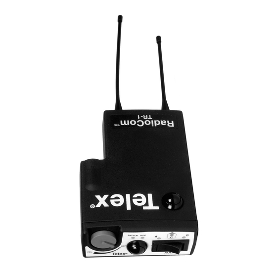
TR-1 Controls and Connections
1. On/Off & Volume Control - Turns the beltpack power on and controls headset volume.
2. BAT/O.M. Light-
Battery -
Light flashes on power up
Light on continuously
Light does not flash or come on
Overmodulation- Light flashes on loudest speech
Light flashes on all speech
Light never flashes on loudest speech
3. Talk Light -
Light on if talk button active.
4. Talk Button -
Press to enable the audio path from the headset.
Selectable modes:
5. A and B Lights - "A" light is on if selection switch in A position.
"B" light is on if selection switch in B position.
6. Selection Switch- Switches between base station presets A or B.
7. "C" Pushbutton - Press to enable the base station "C" presets.
Selectable modes:
8. "C" Button Light - "C" light is on if "C" pushbutton active.
TR-1 Quick Start Procedure
1. Press [MENU] as powering-up the base station.
(Sets unit to Group 01, TX Channel A, RX Channel 01).
2. Press [MENU] as powering-up the beltpack.
(Sets unit to Group 01, RX Channel A, TX Channel 01).
3. Press [MENU] until you arrive at the encryption code screen. Hit [SET] to begin editing the
4-digit encryption code. Set the code that you wish.
4. When finished with the encryption code, press and hold [MENU] + [ ] for 3 seconds on the
beltpack. Then set the 4-digit base serial number on the beltpack's display.
(Sets beltpack encryption to only communicate to that base station, no matter how the
encryption code is set).
5. At the base station, set the 4-digit encryption code to match the beltpack.
6. The base should now indicate a battery voltage and signal strength indicating the base and
beltpack are communicating.
7. Plug a headset into the base and beltpack. Adjust the microphone gain so the overmodulation
light flashes red only on the loudest speech.
Special Key Functions
ClearScan . . . . . . . Press and hold [MENU] + [SET] buttons for 3 seconds to enter the
ClearScan type select. Select from: scan for best group, scan within a
group or scan band.
Lockout . . . . . . . . . Press and hold [ ] + [ ] buttons for 3 seconds. Repeat to toggle it off/on.
1st Use Default . . . Press [MENU] as powering-up the beltpack. Sets beltpack on Group 01,
TX channel 01, RX channel A. All user-programmed memory is retained.
Factory Default . . . Press and hold [MENU]+[SET]+[
grammed memory is erased. Sets beltpack on Group 01, TX channel 01,
RX channel A and all settings change to factory settings.
Software/Ch Maps. . Press and hold [ ] for 3 seconds. The software version of the beltpack will
be displayed for as long as the [ ] arrow is held. When released, the RX
channel map version will be displayed for 1 second then the TX channel
map for 1 second.
Base Serial
Number . . . . . . . . . Press and hold [MENU] + [ ] for 3 seconds in the encryption set screen.
Auto
Program . . . . . . . . Press and hold [ ] for 3 seconds. Allows user to turn auto frequency
programming of the beltpack from the base on or off.
Button Modes
Talk Button . . . . . . Press and hold [SET] then press the talk button. Set talk button to desired
function: latching, off, or push-to-talk.
"C" Button . . . . . . Press and hold [SET] then press the "C" button. Set "C" button to desired
function: momentary, latching, quarterback, off, push-to-talk, latching talk.
TR-1 Quick Start Card
= Battery OK
= Battery Low
= Battery Dead
= Gain OK
= Gain too high
= Gain too Low
Push-to-Talk
Push-to-Latch
Off
Momentary, Latching
Quarterback, Off
Push-to-Talk, Latching Talk
]+[
] for 3 seconds. All user-pro-
9. [MENU] and [SET] buttons - Used to select menus and set options on the LCD.
10. LCD display.
11. [UP] and [DOWN] buttons - Used to select menus and set options on the LCD.
12. Push-to-Talk/Push-to-Transmit Switch -
PT TALK (Push-to-Talk) - The transmitter is always on.
No audio is sent unless the talk button is active. Recommended position.
PT TX (Push-to-Transmit) - The transmitter and audio path are off
except when the talk button is active.
13. Headset Connector- Male XLR connector for Telex units,
Female XLR connector for RTS units.
14. Battery Latch - Press down to enable the battery pack to be released. While the latch is held
down, slide the battery pack about 1/8 inch back, toward the latch, until it stops, then lift out.
15. Receive and Transmitter Antennas - The antennas are screw type, 1/4 wave, replaceable
antennas. The color dot on the screw end of the antenna must match color dot on antenna
receptacle.
Battery Installation
Ensure that the On/Off volume control knob is turned off.
Press and hold down the battery release latch, slide the battery
pack about 1/8 inch back, toward the latch, until it stops.
Then lift battery pack out. Replace batteries as follows:
1. Open the battery pack by inserting
finger nail and lifting.
2. Pull battery strap to remove low
or dead batteries.
4. Start loading at the end of the case where
5. Be sure strap goes under batteries.
6. Tuck end of strap under door
when placing the battery cover
back on the case.
3. Load new batteries following the
polarity as shown in battery case.
the strap is attached to the case.
WARNING
Do not place an alkaline
TR battery pack in any
battery charger. Severe
charger and battery pack
damage may result.
PN 803931 Rev. B
FEB 2005
Advertisement
Table of Contents


Need help?
Do you have a question about the TR-1 and is the answer not in the manual?
Questions and answers