ComfortStar TPA-12 Owner's Manual & Installation Manual
Four-way cassette type air conditioner
Hide thumbs
Also See for TPA-12:
- Service manual (264 pages) ,
- Installation manual (18 pages) ,
- User manual (10 pages)
Table of Contents
Advertisement
Quick Links
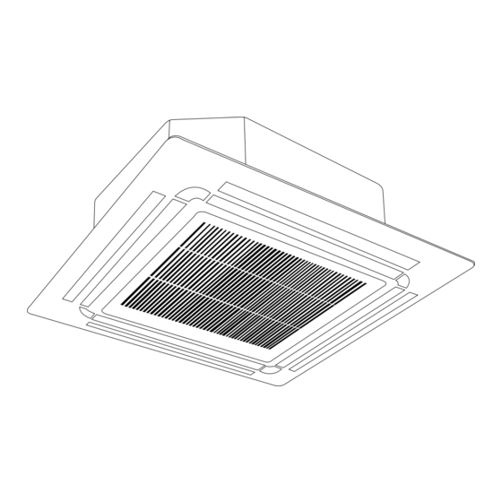
FOUR-WAY CASSETTE TYPE AIR CONDITIONER
Owner's Manual &
Installation Manual
TPA-09 TPA-12 TPA-18 TIP24 TIP36 TIP48
CZP09CD(O) CZP12CD(O) CZP18CD(O) CZP24CD(O) CZP36CD(O) CZP48CD(O)
CZP60CD(O) CHF09CD(O) CHF12CD(O) CHF18CD(O) CHF24CD(O) CHF36CD(O)
CHF48CD(O)
IMPORTANT NOTE:
Read this manual and SAFETY MANUAL(if any)
carefully before installing or operating your new
air conditioning unit. Make sure to save this
manual for future reference.
Please check the applicable models, technical
data, F-GAS(if any) and manufacturer information
from the "Owner's Manual - Product Fiche "
in the packaging of the outdoor unit.
(European Union products only)
Advertisement
Table of Contents

Related Manuals for ComfortStar TPA-12


Summary of Contents for ComfortStar TPA-12
- Page 1 FOUR-WAY CASSETTE TYPE AIR CONDITIONER Owner’s Manual & Installation Manual TPA-09 TPA-12 TPA-18 TIP24 TIP36 TIP48 CZP09CD(O) CZP12CD(O) CZP18CD(O) CZP24CD(O) CZP36CD(O) CZP48CD(O) CZP60CD(O) CHF09CD(O) CHF12CD(O) CHF18CD(O) CHF24CD(O) CHF36CD(O) CHF48CD(O) IMPORTANT NOTE: Read this manual and SAFETY MANUAL(if any) carefully before installing or operating your new air conditioning unit.
-
Page 2: Table Of Contents
Table of Contents Safety Precautions ................04 Owner’s Manual Unit Specifications and Features ............08 1. Indoor unit display................................08 2. Operating temperature..............................10 3. Other features ..................................11 Care and Maintenance ..............12 Troubleshooting ................14... - Page 3 Installation Manual Accessories ...................17 Installation Summary ................18 Unit Parts ....................19 Indoor Unit Installation ...............21 1. Select installation location..............................21 2. Hang indoor unit..................................23 3. Drill wall hole for connective piping..........................25 4. Connect drain hose...................................26 Outdoor Unit Installation................ 1. Select installation location..............................28 2.
-
Page 4: Safety Precautions
Safety Precautions Read Safety Precautions Before Operation and Installation Incorrect installation due to ignoring instructions can cause serious damage or injury. The seriousness of potential damage or injuries is classified as either a WARNING or CAUTION. CAUTION WARNING This symbol indicates the possibility of This symbol indicates the possibility property damage or serious consequences. - Page 5 CLEANING AND MAINTENANCE WARNINGS Turn o the device and disconnect the power before cleaning. Failure to do so can cause • electrical shock. Do not clean the air conditioner with excessive amounts of water. • Do not clean the air conditioner with combustible cleaning agents. Combustible cleaning agents •...
-
Page 6: Owner's Manual
WARNINGS FOR PRODUCT INSTALLATION 1. Installation must be performed by an authorized dealer or specialist. Defective installation can cause water leakage, electrical shock, or re. 2. Installation must be performed according to the installation instructions. Improper installation can cause water leakage, electrical shock, or re. (In North America,installation must be performed in accordance with the requirement of NEC and CEC by authorized personnel only.) 3. - Page 7 WARNING for Using R32/R290 Refrigerant When ammable refrigerant are employed, appliance shall be stored in a well -ventilated area where the room size corresponds to the room area as speci ec for operation. For R32 frigerant models: Appliance shall be installed, operated and stored in a room with a oor area larger than X m²...
-
Page 8: Unit Specifications And Features
Unit Specifications and Features Indoor unit display NOTE: Di erent models have di erent display panel. Not all the indicators describing below are available for the air conditioner you purchased. Please check the indoor display panel of the unit you purchased. Illustrations in this manual are for explanatory purposes. - Page 9 (A-3) Display panel Infrared Manual display receiver button Louver Air outlet Air inlet Operation Timer Alarm indicator indicator indicator PRE-DEF (pre-heating/defrost) indicator Display panel Electric heating indicator Alarm indicator ( some models) When wireless control LED display feature is activated ( some models) Timer PRE-DEF indicator...
-
Page 10: Operating Temperature
Operating temperature When your air conditioner is used outside of the following temperature ranges, certain safety protection features may activate and cause the unit to disable. COOL mode T mode Y mode FOR OUTDOOR UNITS WITH BASEPAN HEATER 17°C - 32°C 0°C - 30°C 10°C - 32°C OR CRANKCASE HEATER... -
Page 11: Other Features
Other features Default Setting Louver Angle Memory Function (some models) When the air conditioner restarts after a power Some models are designed with a louver angle failure, it will default to the factory settings memory function. When the unit restarts after a (AUTO mode, AUTO fan, 24°C (76°F)). -
Page 12: Care And Maintenance
Care and Maintenance If using water, the inlet side If using a vacuum cleaner, the inlet Cleaning Your Indoor Unit should face down and away side should face the vacuum. from the water stream. BEFORE CLEANING OR MAINTENANCE ALWAYS TURN OFF YOUR AIR CONDITIONER SYSTEM AND DISCONNECT ITS POWER SUPPLY BEFORE CLEANING OR MAINTENANCE. - Page 13 Maintenance – Long Periods of Non-Use If you plan not to use your air conditioner for an extended period of time, do the following: Turn on FAN function until Clean all lters unit dries out completely Turn o the unit and Remove batteries disconnect the power from remote control...
-
Page 14: Troubleshooting
Troubleshooting SAFETY PRECAUTIONS If any of the following conditions occurs, turn o your unit immediately! The power cord is damaged or abnormally warm • You smell a burning odor • The unit emits loud or abnormal sounds • A power fuse blows or the circuit breaker frequently trips •... - Page 15 Issue Possible Causes The outdoor unit The unit will make di erent sounds based on its current operating mode. makes noises Dust is emitted from The unit may accumulate dust during extended periods of non-use, which will be either the indoor or emitted when the unit is turned on.
- Page 16 Problem Possible Causes Solution Wait for the power to be restored Power failure The power is turned o Turn on the power The fuse is burned out Replace the fuse The unit is not working Replace batteries Remote control batteries are dead The Unit’...
-
Page 17: Accessories
Accessories The air conditioning system comes with the following accessories. Use all of the installation parts and accessories to install the air conditioner. Improper installation may result in water leakage, electrical shock and re, or cause the equipment to fail. The items are not included with the air conditioner must be purchased separately. -
Page 18: Installation Summary
Installation Summary Install the indoor unit Install the drainpipe Install the outdoor unit Evacuate the refrigeration Connect the wires Connect the refrigerant system pipes Install the front panel Perform a test run Page 18 ... -
Page 19: Unit Parts
Unit Parts NOTE: The installation must be performed in accordance with the requirement of local and national standards. The installation may be slightly di erent in di erent areas. Air outlet Air inlet Front grille Display panel Remote controller Drain pipe Connecting pipe Air inlet Air outlet... - Page 20 Air outlet Air inlet Front grille Display panel Remote controller Drain pipe Connecting pipe Air inlet Air outlet NOTE ON ILLUSTRATIONS Illustrations in this manual are for explanatory purposes. The actual shape of your indoor unit may be slightly di erent. The actual shape shall prevail. ...
-
Page 21: Indoor Unit Installation
Indoor Unit Installation Installation Instructions – Indoor unit NOTE: Panel installation should be performedafter piping and wiring have been completed. Step 1: Select installation location DO NOT install unit in the following Before installing the indoor unit, you must locations: choose an appropriate location. - Page 22 Distance from ceiling relative to height of indoor unit TYPE MODEL Length of A (mm/inch) Length of H (mm/inch) Length of B (mm/inch) 18-24 205/8 > 235/9.3 245/9.6 > 275/10.8 Super-Slim 880/34.5 205/8 > 235/9.3 models 30-48 245/9.6 > 275/10.8 48-60 287/11.3 >...
-
Page 23: Hang Indoor Unit
Step 2: Hang indoor unit 1. Use the included paper template to cut a rectangular hole in the ceiling, leaving at least 1m (39”) on all sides. The cut hole size should be 4cm(1.6”) larger than the boby size. Be sure to mark the areas where ceiling hook holes will be drilled. Drain hose side Refrigerant piping side Refrigerant piping side Drain hose side... - Page 24 5. Mount the indoor unit. You will need two people to lift and secure it. Insert suspension Refrigerant piping side Drain hose side bolts into the unit’ s hanging holes. Fasten them using the included washers and nuts. 770mm / 30.3” (Suspension bolt) 830mm / 32.7”(Body) 900mm / 35.4”(Ceiling opening) 950mm / 37.4”(Panel)
-
Page 25: Drill Wall Hole For Connective Piping
NOTE FOR NEW HOME INSTALLATION When installing the unit in a new home, the NOTE: The bottom of the unit should be ceiling hooks can be embedded in advance. 10-25mm(0.4-0.98”)higher than the ceiling Make sure that the hooks do not come loose board. -
Page 26: Connect Drain Hose
Indoor Drainpipe Installation CAUTION Install the drainpipe as illustrated in the following When drilling the wall hole, make sure to Figure. avoid wires, plumbing, and other sensitive Drain hose Wall Outdoor Indoor Insulation Drainpipe Metal clamp connecting port 1-1.5m (39-59”) ≈... - Page 27 NOTE ON DRAINPIPE INSTALLATION • When using an extended drainpipe, tighten 0-53cm (20.8”) the indoor connection with an additional protection tube to prevent it from pulling loose. The drainpipe should slope downward at a ≥10cm • (4”) gradient of at least 1/100 to prevent water from owing back into the air conditioner.
-
Page 28: Outdoor Unit Installation
Outdoor Unit Installation Install the unit by following local codes and install unit in the following locations: DO NOT regulations , there may be di er slightly Near an obstacle that will block air inlets between di erent regions. and outlets Near a public street, crowded areas, or where noise from the unit will disturb others Near animals or plants that will be harmed... -
Page 29: Install Drain Joint
Step 2: Install drain joint(Heat pump unit only) Step 3: Anchor outdoor unit Before bolting the outdoor unit in place, you must The outdoor unit can be anchored to the install the drain joint at the bottom of the unit. ground or to a wall-mounted bracket with Note that there are two di erent types of drain bolt(M10). - Page 30 Rows of series installation (unit: mm/inch) The relations between H, A and L are Outdoor Unit Dimensions Mounting Dimensions as follows. W x H x D Distance A Distance B 760x590x285 (29.9x23.2x11.2) 530 (20.85) 290 (11.4) 810x558x310 (31.9x22x12.2) 549 (21.6) 325 (12.8) 25 cm / 9.8”...
-
Page 31: Refrigerant Piping Connection
Refrigerant Piping Connection When connecting refrigerant piping, do not let substances or gases other than the speci ed refrigerant enter the unit. The presence of other gases or substances will lower the unit’ s capacity, and can cause abnormally high pressure in the refrigeration cycle. This can cause explosion and injury. -
Page 32: Connection Instructions -Refrigerant Piping
Step 2: Remove burrs. Connection Instructions – Burrs can a ect the air-tight seal of refrigerant Refrigerant Piping piping connection. They must be completely removed. CAUTION 1. Hold the pipe at a downward angle to prevent burrs from falling into the pipe. The branching pipe must be installed •... -
Page 33: Connect Pipes
5. While rmly gripping the nut, use a torque Place aring tool onto the form. wrench to tighten the are nut according Turn the handle of the aring tool to the torque values in above table. clockwise until the pipe is fully ared. NOTE: Use both a spanner and a torque wrench Flare the pipe in accordance with the when connecting or disconnecting pipes to/from... -
Page 34: Installation Of The Throttle. (Some Models)
7. Thread this pipeline through the wall and Precautions connect it to the outdoor unit. • For ensuring throttled e ciency, please 8. Insulate all the piping, including the valves of mount the throttle as horizontally as possible. the outdoor unit. 9. -
Page 35: Wiring
Wiring BEFORE PERFORMING ANY Make sure that you do not cross your electrical wiring with your signal wiring. ELECTRICAL WORK, READ THESE This may cause distortion and REGULATIONS interference. 1. All wiring must comply with local and national The unit must be connected to the electrical codes, regulations and must be main outlet. -
Page 36: Outdoor Uint Wiring
Outdoor Unit Wiring Air switch (purchased seperately) Indoor unit power wires WARNING Before performing any electrical or wiring work, turn o the main power to the system. Indoor unit 1. Prepare the cable for connection Outdoor unit a. You must rst choose the right cable size. -
Page 37: Indoor Uint Wiring
2. Remove the electric cover of the outdoor unit. Super-Slim models If there is no cover on the outdoor unit, take o the bolts from the maintenance board and remove the protection board. Control box Cover Wire outlet Control box Screw 3. - Page 38 CAUTION While connecting the wires, please strictly follow the wiring diagram. • The refrigerant circuit can become very hot. Keep the interconnection cable away from the • copper tube. 5. Clamp down the cable with the cable clamp.The cable must not be loose or pull on the u-lugs. 6.
- Page 39 Independent Power Supply Specifications ≤18K MODEL(Btu/h) 19K~24K 25K~36K 37K~48K 49K~60K PHASE 1 Phase 1 Phase 1 Phase 1 Phase 1 Phase POWER (indoor) 208-240V 208-240V 208-240V 208-240V 208-240V VOLT CIRCUIT BREAKER/ 15/10 15/10 15/10 15/10 15/10 FUSE(A) PHASE 1 Phase 1 Phase 1 Phase 1 Phase...
-
Page 40: Air Evacuation
Air Evacuation Close the Low Pressure side of the manifold Preparations and Precautions gauge, and turn o the vacuum pump. Air and foreign matter in the refrigerant circuit can Wait for 5 minutes, then check that there cause abnormal rises in pressure, which can damage has been no change in system pressure. -
Page 41: Note On Adding Refrigerant
Note on Adding Refrigerant Some systems require additional charging depending on pipe lengths. The standard pipe length varies according to local regulations. For example, in North America, the standard pipe length is 7.5m (25’). In other areas, the standard pipe length is 5m (16‘). The refrigerant should be charged from the service port on the outdoor unit’... -
Page 42: Panel Installation
Panel Installation Adjust the panel by turning it to the arrowed CAUTION direction so that the ceiling opening is completely covered. DO NOT place the panel facedown on the Latch floor, against a wall, or on uneven surfaces. Piping side Drain side Super-Slim models Step 1: Remove the front grille. - Page 43 Water condensation Decoration panel CAUTION Failure to tighten screws can cause water Screws (M5) leakage. (supplied with the panel) Loosen upper nut After installing the decoration panel, ensure that there is no space between the unit body and decoration panel. Otherwise air may leak through the gap and cause dewdrop.
- Page 44 Step 3: Install the panel Step 5: Fasten the control box lid with 2 screws . Align the front panel to the main body, taking into account the position of the piping and drain sides. Hang the four latches of the decorative panel to the hooks of the indoor unit.
- Page 45 NOTE: If the height of the indoor unit needs Hang the intake grille on the panel, and then to be adjusted, you can do so through the connect the lead connectors of the louver motor and the control box on the panel to the openings at the panel’...
-
Page 46: Test Run
Test Run f. Check to see that the drainage system is Before Test Run unimpeded and draining smoothly. A test run must be performed after the entire g. Ensure there is no vibration or abnormal system has been completely installed. Confirm noise during operation. -
Page 47: Packing And Unpacking The Unit
Packing and unpacking the unit Instructions for packing unpacking the unit: Unpacking: Indoor unit: 1.Cut the packing belt. 2. Unpack the package. 3. Take out the packing cushion and packing support. 4. Remove the packing lm. 5. Take out the accessories. 6.
Need help?
Do you have a question about the TPA-12 and is the answer not in the manual?
Questions and answers