Table of Contents
Advertisement
Advertisement
Table of Contents

Related Manuals for Xylem Flygt 2400


Summary of Contents for Xylem Flygt 2400
- Page 1 Installation, Operation, and Maintenance Manual Flygt 2400...
-
Page 3: Table Of Contents
The Ex approval plate........................13 The MSHA approval plate......................14 Product denomination........................14 Installation.............................15 Install the pump..........................15 Sedimentation prevention......................15 Fasteners............................15 Install with S-installation.........................16 Make the electrical connections......................16 General precautions........................16 Requirements..........................17 Cables..............................17 Earthing (Grounding)........................18 Earth (ground) conductor length....................18 Flygt 2400 Installation, Operation, and Maintenance Manual... - Page 4 The pump starts-stops-starts in rapid sequence................39 The pump runs but the motor protection trips................40 The pump delivers too little or no water..................40 Technical Reference..........................42 Application limits..........................42 Motor data............................42 Specific motor data...........................42 Dimensions and weights........................43 Performance curves..........................46 Flygt 2400 Installation, Operation, and Maintenance Manual...
-
Page 5: Introduction And Safety
A hazardous situation which, if not avoided, could result WARNING: in death or serious injury A hazardous situation which, if not avoided, could result CAUTION: in minor or moderate injury Flygt 2400 Installation, Operation, and Maintenance Manual... -
Page 6: Product Warranty
• All service and repair work is done by Xylem-authorized personnel. • Genuine Xylem parts are used. • Only Ex-approved spare parts and accessories authorized by Xylem are used in Ex- approved products. Limitations The warranty does not cover defects caused by these situations: •... -
Page 7: Spare Parts
This includes any modification to the equipment or use of parts not provided by Xylem. If there is a question regarding the intended use of the equipment, please contact an Xylem representative before proceeding. -
Page 8: Hazardous Liquids
These are the personnel requirements for Ex-approved products in potentially explosive atmospheres: • All work on the product must be carried out by certified electricians and Xylem- authorized mechanics. Special rules apply to installations in explosive atmospheres. • All users must know about the risks of electric current and the chemical and physical characteristics of the gas, the vapor, or both present in hazardous areas. -
Page 9: Guidelines For Compliance
Compliance is fulfilled only when you operate the unit within its intended use. Do not change the conditions of the service without the approval of an Xylem representative. When you install or maintain explosion proof products, always comply with the directive and applicable standards (for example, IEC/EN 60079–14). -
Page 10: Environmental Safety
• Clean up all spills in accordance with safety and environmental procedures. • Report all environmental emissions to the appropriate authorities. WARNING: Do NOT send the product to the Xylem manufacturer if it has been contaminated by any nuclear radiation. Inform Xylem so that accurate actions can take place. Electrical installation For electrical installation recycling requirements, consult your local electric utility. -
Page 11: Transportation And Storage
• Do not attach sling ropes to shaft ends. Temperature ranges for transportation, handling and storage Handling at freezing temperature At temperatures below freezing, the product and all installation equipment, including the lifting gear, must be handled with extreme care. Flygt 2400 Installation, Operation, and Maintenance Manual... -
Page 12: Unit In As-Delivered Condition
• Before operating the unit after storage, it must be inspected with special attention to the seals and the cable entry. • The impeller/propeller must be rotated every other month to prevent the seals from sticking together. Flygt 2400 Installation, Operation, and Maintenance Manual... -
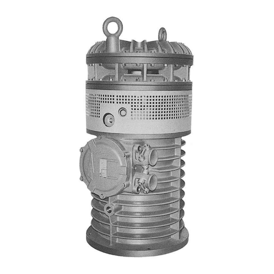
Page 13: Product Description
Application limits (page 42). If there is a question regarding the intended use of the equipment, please contact an Xylem representative before proceeding. WARNING: In explosive or flammable environments, only use Ex- or MSHA-approved pumps. -
Page 14: Monitoring Equipment
18. Duty factor 19. Product weight 20. Locked rotor code letter 21. Power factor 22. Maximum ambient temperature 23. Read installation manual 24. Notified body. Only for EN-approved Ex-products Figure 1: The data plate Flygt 2400 Installation, Operation, and Maintenance Manual... -
Page 15: The Ex Approval Plate
3. Approved for drive unit 4. Stall time 5. Starting current/Rated current 6. Duty class 7. Duty factor 8. Input power 9. Rated speed 10. Controller 11. Additional information 12. Max. ambient temperature 13. Serial number Flygt 2400 Installation, Operation, and Maintenance Manual... -
Page 16: The Msha Approval Plate
The serial number is used for identification of an individual product, and is divided into four parts. This is an example of a serial number, and an explanation of its parts. NP 3085.183 - 951 0163 Product code Production year Production cycle Running number Flygt 2400 Installation, Operation, and Maintenance Manual... -
Page 17: Installation
2.5 (8.2) Water + sand, particle size <0.1 mm (0.004 in) 1.5 (4.9) For more permanent installations with a heavily contaminated pumped liquid, a settling pump-sump is recommended. Figure 4: Settling pump-sump Fasteners Flygt 2400 Installation, Operation, and Maintenance Manual... -
Page 18: Install With S-Installation
• There is a risk of electrical shock or explosion if the electrical connections are not correctly carried out or if there is fault or damage on the product. WARNING: Do not install the starter equipment in an explosive zone unless it is explosion-proof rated. Flygt 2400 Installation, Operation, and Maintenance Manual... -
Page 19: Requirements
• If the motor cable has to be lengthened, splice it with the type of cast resin or shrinking sleeves permitted for explosive areas and with explosion-proof connection boxes. Follow the instructions from the manufacturer. Flygt 2400 Installation, Operation, and Maintenance Manual... -
Page 20: Earthing (Grounding)
7. Fasten the screws on the entrance flange so that the cable insertion assembly bottoms out. After you have connected the motor cable to the pump, connect the motor cable and the control cable to the starter equipment. Flygt 2400 Installation, Operation, and Maintenance Manual... -
Page 21: Cable Charts
Thermal detector in main bearing Pump Jumper Crimp connection Terminal board, terminal plate Crimp isolation Leakage sensor Motor protector Stator leads (U1, U2, U5, U6, V1, V2, V5, V6, W1, W2, W5, W6, Z1, Z5, Z6) Flygt 2400 Installation, Operation, and Maintenance Manual... -
Page 22: Color Code Standard
Installation Color code standard Code Description Brown Black White Orange Green GNYE Green-Yellow Grey Blue Yellow Flygt 2400 Installation, Operation, and Maintenance Manual... -
Page 23: View Of Terminal Board And Sensor Connections
MAX 10A, cos =1 MAX 2,5V THERMAL DETECTOR IN MAIN BEARING ALT. CONNECTION AT 2 LEADER PILOT CABLE THERMAL MAX 2,5V DETECTORS IN STATOR THERMAL D (DELTA) Y (STAR) DETECTOR IN JUMPERS JUMPERS MAIN BEARING Flygt 2400 Installation, Operation, and Maintenance Manual... -
Page 24: Motor Cable, Stator Leads And Thermal Contacts Connection To Terminal Board
W1 W5 W1 V6 W1 W5 U2,U6 U6 V6 W6 W2 W6 V1,V5 U2 U6 V2,V6 U2 V2 W2 V2 V6 W1,W5 ALT. T1 W2,W6 ALT. T2 T1,T2 WH/YE ALT. T3, T4 ALT. Flygt 2400 Installation, Operation, and Maintenance Manual... -
Page 25: Check The Impeller Rotation
• If the motor has a 3-phase connection, then transpose two phase conductors and repeat this procedure from step 1. For 3-phase pumps with external starters or without built-in motor protection, the phases must be shifted on the output terminal of the starter. Flygt 2400 Installation, Operation, and Maintenance Manual... -
Page 26: Operation
Make sure that you understand the noise level requirements in the environment where the pump is installed. Failure to do so may result in hearing loss or violation of local laws. Start the pump Flygt 2400 Installation, Operation, and Maintenance Manual... -
Page 27: Clean The Pump
Let the pump run for a while in clean water, or flush it through the discharge connection. Flygt 2400 Installation, Operation, and Maintenance Manual... -
Page 28: Maintenance
15 (11) 27 (20) 65 (48) 127 (93.7) 220 (162) 434 (320) 70, 80 2.7 (2) 5.4 (4) 9.0 (6.6) 22 (16) 44 (32) 76 (56) 187 (138) 364 (268) 629 (464) 1240 (915) Flygt 2400 Installation, Operation, and Maintenance Manual... -
Page 29: Service
Check that all screws, bolts, and nuts are properly tightened. the pump and Check the condition of lifting handles, eye bolts, ropes, chains, and wires. installation Check for worn or damaged parts. Adjust and/or replace if necessary. Flygt 2400 Installation, Operation, and Maintenance Manual... - Page 30 Contact an electrician, if necessary. Regardless of individual applications, the inspection chamber should not be inspected less frequently than the intervals for normal applications and operating conditions at media (liquid) temperatures <40°C (104°F). Flygt 2400 Installation, Operation, and Maintenance Manual...
-
Page 31: Major Overhaul
2. Let the oil run out. Fill with oil 1. Remove the oil level screw. 2. Fill with new oil until it pours out from the oil level hole. Quantity: 11.4 L (12 qt.) Flygt 2400 Installation, Operation, and Maintenance Manual... -
Page 32: Replace The Impeller
2. Insert a sling into the lifting eyes and lift away the upper diffuser ring. Note that the outer diffuser disc follows with it. 3. Remove the impeller: a) Remove the impeller screw and the washer. Flygt 2400 Installation, Operation, and Maintenance Manual... - Page 33 Remove the diffuser disc by removing the screw. 6. Remove the sleeve. If it is tight, use a puller. It may come loose when the inner impeller is prized loose in the same way as the outer. Flygt 2400 Installation, Operation, and Maintenance Manual...
-
Page 34: Remove The Impeller: Mt
A worn impeller and/or pump housing can have very sharp edges. Wear protective gloves. 1. Remove the strainers. 2. Remove the outer suction cover and the impeller. WS001901A Use a three-shanked puller if necessary. Flygt 2400 Installation, Operation, and Maintenance Manual... -
Page 35: Install The Impeller: Ht
Fit an appropriate number of adjusting washers on the shaft. WS001887A 2. Place the rubber-coated diffuser ring in position, and tighten it temporarily with a few bolts so that it is properly positioned. This is important for the following impeller adjustment. Flygt 2400 Installation, Operation, and Maintenance Manual... - Page 36 The assembly sleeve is used to give the adjusting washers the right thrust. 4. Measure the clearance: a) Without disturbing the position of the screw, move the adjusting tool from the diffuser disc to the impeller while turning the tool 180°. Flygt 2400 Installation, Operation, and Maintenance Manual...
-
Page 37: Install The Impeller: Mt
Install the impeller: MT 1. Fit the sleeve and the keys onto the shaft. WS001896A 2. Fit the inner suction cover onto the pump casing. Check that the O-ring is lubricated and in place. Flygt 2400 Installation, Operation, and Maintenance Manual... - Page 38 Tightening torque: 200 Nm (150 ft-Ibs) c) Finely adjust the inner suction cover against the impeller using the nuts so that a minimum and uniform clearance is obtained between the impeller and the suction cover. Flygt 2400 Installation, Operation, and Maintenance Manual...
- Page 39 WS001904A 7. Fit the strainers. WS001897A In order for the pump to perform at maximum capacity, the impeller must be adjusted regularly. Flygt 2400 Installation, Operation, and Maintenance Manual...
-
Page 40: Troubleshooting
• All fuses have power and that they are securely fastened to the fuse holders. • The overload protection is not tripped. • The motor cable is not damaged. The impeller is stuck. Clean: Flygt 2400 Installation, Operation, and Maintenance Manual... -
Page 41: The Pump Does Not Stop When A Level Sensor Is Used
• The impeller • The sump in order to prevent the impeller from clogging again. If the problem persists, contact the local Xylem service shop. Always state the serial number of your pump when you contact Xylem, see Product Description (page 11). -
Page 42: The Pump Runs But The Motor Protection Trips
There is a malfunction in the Replace the overload protection. overload protection. If the problem persists, contact the local Xylem service shop. Always state the serial number of your pump when you contact Xylem, see Product Description (page 11). - Page 43 • Depending on the installation type, add a means for priming the pump, such as a foot valve. If the problem persists, contact the local Xylem service shop. Always state the serial number of your pump when you contact Xylem, see Product Description (page 11).
-
Page 44: Technical Reference
For specific weight, current, voltage, power rating, and speed of the pump, see the data plate on the pump. For starting current, see Motor data (page 42). For other applications, contact the nearest Xylem representative for information. Motor data Feature Description... -
Page 45: Dimensions And Weights
• Rated output 104 kW (139 hp) Voltage (V) Rated current (A) Starting current (A) 1,195 1,260 1,145 1,105 Dimensions and weights Version code 402/490 All measurements in the illustrations are in millimeters. Figure 6: MT Flygt 2400 Installation, Operation, and Maintenance Manual... - Page 46 Technical Reference Figure 7: HT Table 3: Weight without motor cable 900 kg (1,984 lbs) 985 kg (2,172 lbs) Flygt 2400 Installation, Operation, and Maintenance Manual...
- Page 47 Technical Reference Version code 591 All measurements in the illustrations are in millimeters. Figure 8: MT Flygt 2400 Installation, Operation, and Maintenance Manual...
-
Page 48: Performance Curves
Technical Reference Figure 9: HT Table 4: Weight without motor cable 915 kg (2,017 lbs) 1,000 kg (2,205 lbs) Performance curves Test standard Pumps are tested in accordance with ISO 9906, HI level A. Flygt 2400 Installation, Operation, and Maintenance Manual... - Page 49 Technical Reference Curves [kW] [kW] H [m] H [m] 80 100 120 140 160 Q [l/s] Q [l/s] Figure 10: HT Figure 11: MT Flygt 2400 Installation, Operation, and Maintenance Manual...
- Page 52 For more information on how Xylem can help you, go to xyleminc.com Xylem Water Solutions AB Visit our Web site for the latest version of this document and more information Gesällvägen 33...
Need help?
Do you have a question about the Flygt 2400 and is the answer not in the manual?
Questions and answers