Table of Contents
Advertisement
Quick Links
Advertisement
Table of Contents

Related Manuals for Xylem FLYGT Flygt 2071


Summary of Contents for Xylem FLYGT Flygt 2071
- Page 1 Installation, Operation, and Maintenance Manual Flygt 2071...
-
Page 3: Table Of Contents
Table of Contents Table of Contents Introduction and Safety.........................3 Introduction............................3 Safety terminology and symbols.......................3 Product warranty..........................4 Spare parts............................5 Safety..............................5 User safety............................5 Hazardous liquids..........................6 Wash the skin and eyes........................6 Environmental safety...........................6 Transportation and Storage........................7 Inspect the delivery..........................7 Inspect the package.........................7 Inspect the unit..........................7 Transportation guidelines........................7 Precautions............................7 Position and fastening........................7... - Page 4 Table of Contents Check the impeller rotation......................20 Operation..............................21 Precautions............................21 Distance to wet areas........................21 Noise level............................21 Start the pump...........................21 Clean the pump..........................22 Maintenance............................23 Precautions............................23 Maintenance guidelines........................23 Torque values............................23 Service..............................24 Inspection............................24 Major overhaul..........................26 Change the oil...........................26 Empty the oil...........................26 Fill with oil............................26 Replace the impeller.........................26 Remove the impeller........................26 Install the impeller: MT .........................29...
-
Page 5: Introduction And Safety
Introduction and Safety Introduction and Safety Introduction Purpose of this manual The purpose of this manual is to provide necessary information for: • Installation • Operation • Maintenance CAUTION: Read this manual carefully before installing and using the product. Improper use of the product can cause personal injury and damage to property, and may void the warranty. -
Page 6: Product Warranty
Product warranty Coverage Xylem undertakes to remedy defects in products from Xylem under these conditions: • The faults are due to defects in design, materials, or workmanship. • The faults are reported to an local sales and service representative within the warranty period. -
Page 7: Spare Parts
This includes any modification to the equipment or use of parts not provided by Xylem. If there is a question regarding the intended use of the equipment, please contact a Xylem representative before proceeding. -
Page 8: Hazardous Liquids
• Clean up all spills in accordance with safety and environmental procedures. • Report all environmental emissions to the appropriate authorities. WARNING: Do NOT send the product to the Xylem manufacturer if it has been contaminated by any nuclear radiation. Inform Xylem so that accurate actions can take place. Electrical installation For electrical installation recycling requirements, consult your local electric utility. -
Page 9: Transportation And Storage
Transportation and Storage Transportation and Storage Inspect the delivery Inspect the package 1. Inspect the package for damaged or missing items upon delivery. 2. Note any damaged or missing items on the receipt and freight bill. 3. File a claim with the shipping company if anything is out of order. If the product has been picked up at a distributor, make a claim directly to the distributor. -
Page 10: Unit In As-Delivered Condition
Transportation and Storage Make sure that the product is warmed up to a temperature above the freezing point before starting up. Avoid rotating the impeller/propeller by hand at temperatures below the freezing point. The recommended method to warm the unit up is to submerge it in the liquid which will be pumped or mixed. -
Page 11: Product Description
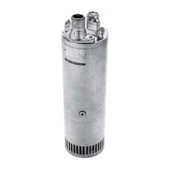
Product Description Product Description Products included Pump model Approvals 2071.010 Standard Pump design The pump is submersible, and driven by an electric motor. Intended use The product is intended for moving waste water, sludge, raw and clean water. Always follow the limits given in Application limits (page 39). -
Page 12: The Data Plate
Product Description The data plate The data plate is a metal label located on the main body of the products. The data plate lists key product specifications. Specially approved products also have an approval plate. Curve code/Propeller code Serial number, see Product denomination (page 10) Product number... - Page 13 Product Description Product code The product code consists of nine characters divided into two parts. This is an example of a product code, and an explanation of its parts. 3085.183 Sales denomination Version Serial number The serial number is used for identification of an individual product, and is divided into four parts.
-
Page 14: Installation
Installation Installation Install the pump WARNING: • Electrical shock hazard. Check that the cable and cable entry have not been damaged during transport before installing the pump. • Make sure that the unit cannot roll or fall over and injure people or damage property. •... -
Page 15: Fasteners
Installation Fasteners WARNING: • Only use fasteners of the proper size and material. • Replace all corroded fasteners. • Make sure that all fasteners are properly tightened and that there are no missing fasteners. Install with S-installation In the S-installation, the pump is transportable and intended to operate either completely or partially submerged in the pumped liquid. -
Page 16: Requirements
Installation CAUTION: If the pump is equipped with automatic level control and/or internal contactor, there is a risk of sudden restart. Requirements These general requirements apply for electrical installation: • The supply authority must be notified before installing the pump if it will be connected to the public mains. -
Page 17: Earthing (Grounding)
Installation Earthing (Grounding) Electrical Hazard: • You must earth (ground) all electrical equipment. This applies to the pump equipment, the driver, and any monitoring equipment. Test the earth (ground) lead to verify that it is connected correctly. • If the motor cable is jerked loose by mistake, the earth (ground) conductor should be the last conductor to come loose from its terminal. -
Page 18: Cable Charts
Installation Cable charts Connection locations L1 L2 L3 T1 T2 T3 T4 Starter equipment and main leads (L1, L2, L3) Coil Earth (ground) Transformer Functional ground Capacitor Control leads (T1, T2, T3, T4) Softstarter Phase shifter Level regulator Diode Contactor, start relay or thermal relay Motor cable, minimum 20 m (66 ft.) Thermal detector in stator Screen... - Page 19 Installation Code Description GNYE Green-Yellow Grey Blue Yellow Flygt 2071 Installation, Operation, and Maintenance Manual...
-
Page 20: View Of Terminal Board And Sensor Connections
Installation View of terminal board and sensor connections Connection plate SENSORS SYMBOLS AND DENOMINATIONS =Terminal board BN=Brown BK=Black =Screen WH=White THERMAL 2071 DETECTORS OG=Orange IN STATOR =Ground GN=Green 2075 GNYE=Green-Yellow MAX 250v =Functional ground 3060 RD=Red MAX 6A, cos =0,6 GY=Grey MAX 10A, cos =1 3080... -
Page 21: Motor Cable, Stator Leads And Thermal Contacts Connection To Terminal Board
Installation Motor cable, stator leads and thermal contacts connection to terminal board MOTOR CABLE CONNECTION TO TERMINAL BOARD 1PH Screen as ground conductor Terminal board A AWG/7 Functional ground to GC FGB 3xA A AWG/3-2-1-GC S3xA+3xA/3+S(4x0,5) HCR6xA 4GA+2x1,5 2071 1 BK 1 WH 2 WH 2 BK... -
Page 22: Check The Impeller Rotation
Installation Check the impeller rotation WARNING: The starting jerk can be powerful. Check the direction of rotation each time the cable has been re-connected and after phase or total supply failure. 1. Start the motor. 2. Stop the motor. 3. Check that the impeller rotates in the correct direction. The correct direction of impeller rotation is clockwise when you look at the pump from above. -
Page 23: Operation
Operation Operation Precautions WARNING: • Never operate the pump without safety devices installed. • Never operate the pump with the discharge valve closed. • Make sure you have a clear path of retreat. • Never work alone. CAUTION: If the pump is equipped with automatic level control and/or internal contactor, there is a risk of sudden restart. -
Page 24: Clean The Pump
Operation WARNING: • If you need to work on the pump, make sure that it is isolated from the power supply and cannot be energized. • Make sure that the unit cannot roll or fall over and injure people or damage property. •... -
Page 25: Maintenance
Maintenance Maintenance Precautions WARNING: • Always follow safety guidelines when working on the product. See Introduction and Safety (page 3). • Disconnect and lock out electrical power before installing or servicing the pump. • Make sure that the unit cannot roll or fall over and injure people or damage property. •... -
Page 26: Service
Maintenance Property class 10.9 4.0 (2.9) 8.1 (6) 14 (10) 33 (24) 65 (48) 114 (84) 277 (204) 541 (399) 935 (689) 1840 (1357) 12.9 4.9 (3.6) 9.7 (7.2) 17 (13) 40 (30) 79 (58) 136 (100) 333 (245) 649 (480) 1120 2210 (825.1) - Page 27 Maintenance Service item Action Wear on the impeller or surrounding parts necessitates fine adjustments of the impeller or replacement of worn parts. Check the water and oil mixture as follows: Insert a tube or hose into the oil hole. Cover the top end of the tube. Take up a little oil from the bottom.
-
Page 28: Major Overhaul
Maintenance Major overhaul For a major overhaul, take this action in addition to the tasks listed under Inspection. Service item Action Support and main bearing Replace the bearings with new bearings. Mechanical seal Replace with new seal units. Change the oil A paraffin oil with viscosity close to ISO VG32 is recommended. - Page 29 Maintenance WS001781A b) Remove the nuts and washers. WS001780A c) Remove the strainer. Use a long M12 screw (427 07 00). WS001783A 3. Remove the diffuser ring: a) Remove the sleeves, nuts, and washers. b) Remove the diffuser ring (MT)/sleeve (LT). Flygt 2071 Installation, Operation, and Maintenance Manual...
- Page 30 Maintenance WS001782A 4. Remove the impeller: a) Lock the impeller to prevent rotation. Use pliers, a screwdriver, or similar. WS001779A b) Remove the impeller screw. c) Remove the washer (and sleeve on LT version). d) Pull off the impeller. Use an impeller puller or pry off carefully with two strong screwdrivers or bars. WS001778A e) Remove the adjusting washers.
-
Page 31: Install The Impeller: Mt
Maintenance Insert a screwdriver or bar in the center hole of the diffuser and carefully pry the diffuser loose. WS001775A c) Pull off the impeller. Use an impeller puller or pry off carefully with two strong screwdrivers or bars. WS001776A d) Remove the adjusting washers. - Page 32 Maintenance WS001771A 2. Fit the impeller onto the shaft. 3. Put the sleeve on the shaft and secure the impeller with the washer and the screw. Check that the impeller is firmly seated. The impeller clearance should be minimal when the impeller is tightened. Use the adjusting washers to adjust the clearance.
- Page 33 Maintenance WS001772A 2. Install the impeller: a) Place the washer on the impeller screw. b) Fit the impeller onto the shaft. c) Tighten the impeller screw. Tightening torque: 20 Nm (15 ft-lbs) The impeller clearance should be minimal when the impeller is tightened. Use the adjusting washers to adjust the clearance.
- Page 34 Maintenance WS0017669A 4. Check that the spacing sleeves are seated in the diffuser ring. 5. Press the diffuser against the impeller. 6. Tighten the adjusting nuts so that they lie flush against the diffuser ring. 7. Back off all adjusting nuts another half turn (counterclockwise). The impeller clearance should be minimal when the impeller is tightened.
-
Page 35: Install The Impeller: Lt
Maintenance WS001773A In order for the pump to perform at maximum capacity, the impeller must be adjusted regularly. Install the impeller: LT 1. Prepare the shaft: a) Polish off any flaws with a fine emery cloth. The end of the shaft must be clean and free from burrs. b) Grease the end of the shaft. - Page 36 Maintenance Pumps equipped with polyurethane covering are extremely resistant to wear. If the impeller does not rotate completely freely, the friction will generate a lot of heat. This can result in deformed wear parts, a stuck impeller, or damage to the pump. The impeller clearance should be 0.2–0.3 mm (0.008–0.012 in.) when the impeller is tightened.
-
Page 37: Troubleshooting
Troubleshooting Troubleshooting Introduction Follow these guidelines when troubleshooting the pump: • Disconnect and lock out the power supply except when conducting checks that require voltage. • Make sure that no one is near the pump when the power supply is reconnected. •... -
Page 38: The Pump Does Not Stop When A Level Sensor Is Used
Troubleshooting Cause Remedy • The impeller • The sump in order to prevent the impeller from clogging again. The start relay or the start capacitor Replace the defective part. is defective (only for 1-phase motor) If the problem persists, contact the local sales and service representative. Always state the serial number of your product, see Product Description (page 9). -
Page 39: The Pump Runs But The Motor Protection Trips
Troubleshooting Cause Remedy The start relay is not correctly set Adjust the start relay. (only for 1-phase motor) The run capacitor is defective (only Replace the run capacitor. for 1-phase motor) If the problem persists, contact the local sales and service representative. Always state the serial number of your product, see Product Description (page 9). -
Page 40: The Pump Delivers Too Little Or No Water
Troubleshooting The pump delivers too little or no water WARNING: Always disconnect and lock out power before servicing to prevent unexpected startup. Failure to do so could result in death or serious injury. NOTICE: Do NOT override the motor protection repeatedly if it has tripped. Doing so may result in equipment damage. -
Page 41: Technical Reference
Technical Reference Technical Reference Application limits Data Description Media (liquid) Standard temperature version: Maximum temperature 40°C (104°F) temperature Warm media (liquid) version: Maximum temperature 70°C (158°F) Warm liquid has certain operational limitations, which are stated on a plate on the pump. - Page 42 Technical Reference Voltage (V) Rated current (A) Starting current (A) 3-phase, 50 Hz Motor type: • 2,800 rpm • Rated output 3.0 kW (4.0 hp) Voltage (V) Rated current (A) Starting current (A) 60.1 34.6 32.9 24.7 27.1 3-phase, 60 Hz Motor type: •...
-
Page 43: Dimensions And Weights
Technical Reference Dimensions and weights Table 3: Dimensions Pressure class 185 mm (7.285 in.) 705 mm (27.75 in.) 185 mm (7.285 in.) 665 mm (26.18 in.) Table 4: Weight without motor cable 28 kg (62 lbs) 31 kg (68 lbs) Performance curves Test standard Pumps are tested in accordance with ISO 9906, HI level A. - Page 44 Technical Reference 2071.010 [kW] / [hp] [kW] H [m] / [ft] H [m] Q [usgpm] / [l/s] Q [l/s] Figure 5: 60 Hz, 1-phase Figure 4: 50 Hz, 3-phase [kW] / [hp] H [m] / [ft] Q [usgpm] / [l/s] Figure 6: 60 Hz, 3-phase Flygt 2071 Installation, Operation, and Maintenance Manual...
- Page 46 For more information on how Xylem can help you, go to xyleminc.com Xylem Water Solutions AB Visit our Web site for the latest version of this document and more information Gesällvägen 33...
Need help?
Do you have a question about the FLYGT Flygt 2071 and is the answer not in the manual?
Questions and answers