Table of Contents
Advertisement
Quick Links
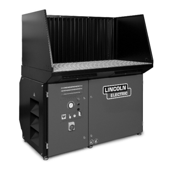
Operator's Manual
DownFlex
Register your machine:
www.lincolnelectric.com/register
Authorized Service and Distributor Locator:
www.lincolnelectric.com/locator
Save for future reference
Date Purchased
Code: (ex: 10859)
Serial: (ex: U1060512345)
IM10013-A
| Issue D ate Mar-18
© Lincoln Global, Inc. All Rights Reserved.
®
200/400
For use with machines having Code Numbers:
K2751-2, K2751-3,
K2751-6, K2751-8
Advertisement
Table of Contents

Subscribe to Our Youtube Channel
Related Manuals for Lincoln Electric K2751-2


Summary of Contents for Lincoln Electric K2751-2
- Page 1 Operator’s Manual ® DownFlex 200/400 For use with machines having Code Numbers: K2751-2, K2751-3, K2751-6, K2751-8 Register your machine: www.lincolnelectric.com/register Authorized Service and Distributor Locator: www.lincolnelectric.com/locator Save for future reference Date Purchased Code: (ex: 10859) Serial: (ex: U1060512345) IM10013-A | Issue D ate Mar-18...
- Page 2 THANK YOU FOR SELECTING A QUALITY PRODUCT BY KEEP YOUR HEAD OUT OF THE FUMES. DON’T get too close to the arc. LINCOLN ELEC TRIC. Use corrective lenses if necessary to stay a reasonable distance away from the arc. READ and obey the Safety Data PLEASE EXAMINE CARTON AND EQUIPMENT FOR Sheet (SDS) and the warning label DAMAGE IMMEDIATELY...
- Page 3 W117.2-1974. A Free copy of “Arc Welding Safety” booklet E205 is available from the Lincoln Electric Company, 2.d. All welders should use the following procedures in order to 22801 St. Clair Avenue, Cleveland, Ohio 44117-1199.
- Page 4 SAFETY ELECTRIC SHOCK ARC RAYS CAN BURN. CAN KILL. 3.a. The electrode and work (or ground) circuits are 4.a. Use a shield with the proper filter and cover plates to protect your electrically “hot” when the welder is on. Do eyes from sparks and the rays of the arc when welding or not touch these “hot”...
- Page 5 SAFETY WELDING AND CUTTING CYLINDER MAY EXPLODE IF SPARKS CAN CAUSE DAMAGED. FIRE OR EXPLOSION. 7.a. Use only compressed gas cylinders containing the correct shielding gas for the process used 6.a. Remove fire hazards from the welding area. If and properly operating regulators designed for this is not possible, cover them to prevent the welding sparks the gas and pressure used.
- Page 6 S FETY As a rule of thumb, for many mild steel electrode, if the air is visibly Ventilation clear and you are comfortable, then the ventilation is generally There are many methods which can be selected by the user to adequate for your work.
- Page 7 TLV and PEL values are as of October 2013. Always check Safety and 313 of the Emergency Planning and Community Right- Data Sheet (SDS) with product or on the Lincoln Electric website at to-Know Act of 1986 and of 40CFR 370 and 372.
-
Page 8: Table Of Contents
TABLE OF CONTENTS Page Installation........................Section A Technical Specifications.......................A-1 General Description......................A-2 Intended Use........................A-2 Components......................... A-2 Installation........................A-3/A-5 Installation Of Remaining Options................. A-5/A-8 Electrical Connection......................A-9 Connection To The Input Power..................A-10 Direction Of Rotation......................A-11 Operation.........................Section B General Description......................B-1 Operation..........................B-1 Safety Precautions....................... B-1 Filter Replacement....................... -
Page 9: Installation
INSTALLATION TECHNICAL SPECIFICATIONS - DOWNFLEX 200/400 DIMENSIONS L x W x H Downdraft Table 54.3 x 39.4 x 36.2 in. (1380 x 1005 x 920 mm) Downdraft Table incl. Backdraft Kit and Side Panels 54.3 x 39.4 x 60.8 in. (1380 x 1005 x 1543 mm) HEIGHT ADJUSTMENT 36 - 38 in. -
Page 10: General Description
INSTALLATION GENERAL DESCRIPTION FIGURE A.1 – COMPONENTS The downdraft table is a workbench with an integrated extraction fan and filtration system that is used for welding, grinding and plasma cutting applications. Depending on the specific application, the use of certain accessories is required and/or recommended. See Accessories section of this manual. - Page 11 INSTALLATION INSTALLATION 4. Tighten the bolts. BACK PANEL TOOLS AND REQUIREMENTS To mount the back panel, proceed as follows. See The following tools and requirements are needed to Figure A.4. install the product: 1. Unscrew the cover strip. • Spanner M6 and M8 2.
- Page 12 INSTALLATION FIGURE A.6 – PLASMA CUTTING WORK GRID FIGURE A.5 – BACKDRAFT KIT PLASMA CUTTING WORK GRID The plasma cutting work grid consists of: • 2 Grid frames 28.9 x 26.3 x 2.5 in. (735 x 669 x 64 mm) •...
-
Page 13: Installation Of Remaining Options
INSTALLATION WORK GRID 3. Unlock the HEPA filter cartridge by pressing a screwdriver or other tool at the position of the strips To mount the standard work grid, proceed as follows. (B) on the top and bottom of unit. See Figure A.8. See Figure A.7. - Page 14 INSTALLATION FIGURE A.8 – HEPA KIT 3. Place bolts halfway through the 2 lower holes at the outlet of the downdraft table or HEPA box (C). See Figure A.9. 4. Place the silencer/outlet duct over the bolts (D). See Figure A.9. 5.
- Page 15 INSTALLATION WORKING LIGHT MOVEMENT SENSOR (DownFlex 400-MS/A only) The working light consists of: • Lighting fixture with 7.5 ft (2.3 m) of cable and plug The movement sensor consists of: • 6 Bolts M6 • Automatic start/stop device with 7.5 ft (2.3 m) of cable and plug •...
- Page 16 INSTALLATION WELDING CABLE SENSOR WHEEL KIT (DownFlex 400-MS/A only) The wheel kit consists of: The welding cable sensor consists of: • 2 Swivel casters with brakes. • Clamp with 7.5 ft (2.3 m) of cable and plug. • 3 Swivel casters without brakes. To mount the welding cable sensor, proceed as To mount the wheel kit, proceed as follows.
-
Page 17: Electrical Connection
INSTALLATION CAUTION WARNING Do not position the product where it is exposed to vibrations or heat radiation from heat sources. Observe the earlier described ambient conditions. ------------------------------------------------------------------------ FIGURE A.14 – CARGO LASHINGS ELECTRICAL CONNECTION CAUTION Make sure that the system is suitable for connec- tion to the local input power. -
Page 18: Connection To The Input Power
INSTALLATION A-10 A-10 FIGURE A.17 – CHANGE OF TRANSFORMER To change the motor from 480V to 208/240V, proceed as follows. 1. Open left door. 2. Loosen 4 screws from motor connection block (A) and remove cover. See Figure A.16. 3. Disconnect the 3 phase wires from the motor connection block. -
Page 19: Direction Of Rotation
INSTALLATION A-11 A-11 WARNING WARNING Be sure to mount the right fuse type. Do not open the door within 20 Plugs/connections to be installed in seconds after switching off the fan. accordance with the National Keep your hands away from the Electrical Code (NEC) and local fan wheel. -
Page 20: Operation
OPERATION GENERAL DESCRIPTION SAFETY PRECAUTIONS WARNING The downdraft table is a workbench with an integrated extraction fan and filtration system that is used for FUMES AND GASES can be welding, grinding and plasma cutting applications. dangerous Depending on the specific application, the use of cer- tain accessories is required and/or recommended. - Page 21 OPERATION WARNING WARNING Moving parts (fan) may cause Never use the product for: injury. After switching off the fan, • Oxy-fuel cutting. wait at least 20 seconds before • Arc-air gouging. opening the door(s) to carry out • Oil mist. service, maintenance or repair jobs.
-
Page 22: Filter Replacement
OPERATION FILTER REPLACEMENT FILTER CARTRIDGES AND PREFILTERS FIGURE B.1 – FILTER REPLACEMENT If the filter cartridges and/or prefilters are damaged or saturated, they need to be replaced. To replace the fil- ter cartridges or prefilters, proceed as follows: WARNING • Always wear face mask and gloves during filter replacement. - Page 23 OPERATION HEPA FILTER (OPTIONAL) The HEPA filter is supplied in a plastic bag and comes with face mask and a pair of disposable gloves. It should be replaced at the same time as the main filter cartridges. WARNING • Always wear face mask and gloves during filter replacement.
-
Page 24: Downflex 200-M (Only
OPERATION DOWNFLEX 200-M (Only) FILTER REPLACEMENT 1. During use, regularly check the Magnehelic gauge CONTROL PANEL (B). When the pressure reaches 0.25 psi (1700 Pa), the filter cartridges need to be replaced. See The control panel is equipped with the following con- Figure B.2. -
Page 25: Downflex 400-Ms/A (Only
OPERATION DOWNFLEX 400-MS/A (Only) AUTOMATIC OFFLINE FILTER CLEANING Each time the downdraft table is switched off, the filter CONTROL PANEL cartridges are automatically cleaned by a full cleaning cycle. This procedure takes approximately 2 minutes, The control panel is equipped with the following con- during which each filter cartridge is cleaned by 10 trols. - Page 26 OPERATION NOTE: When welding/grinding and cleaning is fin- ished turn main disconnect switch (A) off to remove the main input power. FILTER REPLACEMENT When the filter cleaning system is unable to get the pressure below 0.22 psi (1500 Pa) the filter cartridges are probably saturated and need to be replaced.
-
Page 27: Accessories
ACCESSORIES ACCESSORIES E. HEPA Kit Consists of a filter housing with a HEPA filter to be The following products are accessories for the mounted on the outlet of the downdraft table. DownFlex tables: F. Silencer/Outlet Duct CAUTION Consists of a rectangular sheet metal shaft to be mounted on the outlet of the downdraft table or on the Backdraft kit and side panels are standard HEPA kit. - Page 28 ACCESSORIES J. Welding Cable Sensor (DownFlex 400-MS/A only) Metal clamp with built-in sensor that works as an automatic start/stop device. The clamp is to be connected to the ground cable of the welding machine. Suitable for welding applications only. The welding cable sensor operates on the basis of a change in the magnetic field of the ground cable of a welding machine.
-
Page 29: Maintenance
MAINTENANCE SAFETY PRECAUTIONS The indicated maintenance intervals can vary depending on the specific working and ambient WARNING conditions. Therefore, it is recommended to thoroughly inspect the complete product once every year in addition to the indicated periodic maintenance. WARNING Before carrying out service, maintenance and/or repair jobs, fully disconnect power to the machine. -
Page 30: Maintenance
PERIODIC MAINTENANCE MAINTENANCE The maintenance activities in the table below are strictly reserved for well trained and authorized service engineers. TABLE D.1 – MAINTENANCE SCHEDULES FREQUENCY Every Every 2 Every 12 COMPONENT ACTION Week Weeks Months Prefilters (1st Check for damage and correct installation. Replace if necessary. stage) Clean prefilters using an industrial vacuum cleaner. -
Page 31: Troubleshooting Guide
HOW TO USE TROUBLESHOOTING GUIDE WARNING Service and Repair should only be performed by Lincoln Electric Factory Trained Personnel. Unauthorized repairs performed on this equipment may result in danger to the technician and machine operator and will invalidate your factory warranty. For your safety and to avoid Electrical Shock, please observe all safety notes and precautions detailed throughout this manual. - Page 32 TROUBLESHOOTING Observe all Safety Guidelines detailed throughout this manual POSSIBLE PROBLEMS RECOMMENDED CAUSE (SYMPTOMS) COURSE OF ACTION GENERAL Fan does not start running. 1. No power supply. 1. Check power supply. Downdraft table does not function. 2. Turn on main switch. 2.
- Page 33 TROUBLESHOOTING Observe all Safety Guidelines detailed throughout this manual PROBLEMS POSSIBLE RECOMMENDED (SYMPTOMS) CAUSE COURSE OF ACTION DOWNFLEX 400-MS/A ONLY 1. No compressed air available. 1. Connect/repair compressed air Fan does not start running. supply. Downdraft table does not function. 2.
- Page 34 DIAGRAMS FIGURE F.1 – 548677 DOWNFLEX 200-M (208-240V/3~/60HZ) (USA) DOWNFLEX 200/400...
-
Page 35: Downflex 200-M
DIAGRAMS FIGURE F.2 – 548677 DOWNFLEX 200-M (480V/3~/60HZ) (USA) & & & & & & 4" 4" 4" 4" 4" 4" 4" 4" DOWNFLEX 200/400... - Page 36 DIAGRAMS FIGURE F.3 – 548677 DOWNFLEX 200-M (600V/3~/60HZ) (CANADA) DOWNFLEX 200/400...
-
Page 37: Downflex 400-Ms/A
DIAGRAMS FIGURE F.4 – 548636 DOWNFLEX 400-MS/A (208-240V/3~/60HZ) (USA) DOWNFLEX 200/400... - Page 38 DIAGRAMS FIGURE F.5 – 548636 DOWNFLEX 400-MS/A (480V/3~/60HZ) (USA) DOWNFLEX 200/400...
- Page 39 DIAGRAMS FIGURE F.6 – 548636 DOWNFLEX 400-MS/A (600V/3~/60HZ) (USA) DOWNFLEX 200/400...
- Page 40 WARNING Do not touch electrically live parts or Keep flammable materials away. Wear eye, ear and body protection. electrode with skin or wet clothing. Insulate yourself from work and AVISO DE ground. Spanish PRECAUCION No toque las partes o los electrodos Mantenga el material combustible Protéjase los ojos, los oídos y el bajo carga con la piel o ropa moja-...
- Page 41 WARNING Keep your head out of fumes. Turn power off before servicing. Do not operate with panel open or Use ventilation or exhaust to guards off. remove fumes from breathing zone. AVISO DE Spanish PRECAUCION Los humos fuera de la zona de res- Desconectar el cable de ali- No operar con panel abierto o piración.
- Page 42 We respond to our customers based on the best information in our possession at that time. Lincoln Electric is not in a position to warrant or guarantee such advice, and assumes no liability, with respect to such information or advice.
Need help?
Do you have a question about the K2751-2 and is the answer not in the manual?
Questions and answers