
Related Manuals for HURST eDRAULIC SP 333 E2


Summary of Contents for HURST eDRAULIC SP 333 E2
- Page 1 Instruction manual for rescue equipment eDRAULIC spreader SP 333 E2 SP 555 E2 SP 777 E2 271333085 EN Edition 09.2019 replaces 11.2018 (Original instruction manual)
-
Page 2: Table Of Contents
Content Page 1. Danger classifications 2. Product safety 3. Proper use 4. Functional description 4.1 Description 4.2 Unit in detail 4.3 Hydraulic circuit diagram 4.4 Operating movement controls 5. Operation 5.1 Battery or power supply for eDRAULIC device 5.2 Operating the star grip 6. Spreading, pulling, squeezing and peeling 6.1 Safety notes 6.2 Spreading 6.3 Pulling... - Page 3 Content Page 10. Troubleshooting 11. Technical data 11.1 eDRAULIC spreader 11.2 Peeling 11.3 Noise emission (based on standard EN ISO 3744) 11.4 Operating and storage temperature ranges 11.5 Oscillation / vibration 12. Accessories 12.1 Batteries 12.2 Battery charger 12.3 Power supply 12.4 Chain sets 13. Instructions regarding disposal 14. Notes...
-
Page 4: Danger Classifications
1. Danger classifications We differentiate between various different categories of safety instructions. The table shown below provides an overview of the assignment of symbols (pictograms) and signal words to the specific danger and the possible consequences. Damage / Pictogram Keyword Definition Consequences injury to Death or severe DANGER! Immediate danger injury Potentially Potential death or WARNING! dangerous serious injury situation Less dangerous Minor or slight CAUTION! situation injury Damage to the equipment, Risk of damage damage to the ATTENTION! to property/ environment, environment damage to surroundings Handling tips and No injury/damage other important/ to persons/... -
Page 5: Product Safety
GmbH Safety Instructions for eDRAULIC batteries, including all warnings, cautions and information contained therein before they attempt to use or maintain the equipment or its accessories. Do not attempt to utilize or maintain the equipment, including any accessories, unless you have a qualified trainer show you how to safely and properly use this equipment. The use and operation of the HURST Rescue equipment which is powered by lithium- ion batteries must comply with the Akku Power GmbH Safety Instructions for eDRAULIC batteries which are included with the batteries. To safely operate or maintain the equipment, including accessories, you must read and follow this Instruction Manual and all accessory manuals, in addition to receiving the appropriate safety training. - Page 6 In the event of malfunction, Do not carry out any changes immediately deactivate the (additions or conversions) device and secure it. Repair to the equipment without the fault immediately. obtaining the prior approval of HURST. Observe all safety and danger All safety and danger information on the device and instructions on the device in the operating instructions. must always be complete and in a legible condition. Any mode of operation which Repairs to the equipment compromises the safety and/ may only be carried out by or stability of the device is a trained service technician forbidden! with specific knowledge of the device. Safety devices may never be Only genuine HURST disabled! accessories and spare parts are to be used for repairs.
- Page 7 Please ensure that you do not Please ensure that the become entangled in cables battery contacts are not short- and trip when working with or circuited. transporting the device. The build-up of static charges Only touch broken-off or and therefore possible cut-off parts while wearing sparking must be avoided protective gloves, as the torn / when handling the device. cut edges can be very sharp. The eDRAULIC devices have The eDRAULIC devices are an IP54 protection class. not suitable for underwater They are suitable for use in use. wet weather conditions and are splash proof. The equipment is filled with When working with or storing hydraulic fluid. This hydraulic the equipment, ensure that fluid can be detrimental to the function and the safety health if it is swallowed or of the equipment are not its vapor is inhaled. Direct impaired by the effects of contact with the skin must severe external temperatures be avoided for the same and that the equipment is not reason. Also, when handling damaged in any way. Please hydraulic fluid, note that it can note that the equipment can negatively affect biological also heat up over a long...
- Page 8 Do not expose the Akku Do not attempt to use the Power GmbH lithium-ion HURST Rescue Equipment battery to water, oil, or with the Akku Power GmbH moisture or liquid of any kind, lithium-ion battery that as this could lead to a battery has been exposed directly malfunction resulting in fire or indirectly to water, oil, causing personal injury or moisture or liquid of any kind, death! as this could lead to a battery malfunction resulting in fire causing personal injury or death! Do not expose the Akku Do not place the Akku Power Power GmbH lithium-ion GmbH lithium-ion battery that battery charger to water, oil has been exposed directly or moisture or liquid of any or indirectly to water, oil, kind as this could lead to a moisture or liquid of any kind battery malfunction resulting onto a charger as this could in fire causing personal injury lead to a battery malfunction or death! resulting in fire causing personal injury or death! The generally applicable, legal and other binding national and international regulations pertaining to the prevention of accidents and protection of the environment apply and are to be implemented in addition to the operating instructions.
-
Page 9: Proper Use
3. Proper use HURST eDRAULIC spreaders have been specially designed to rescue or retrieve the bodies of victims of road, rail or aircraft accidents or to be used during rescue operations from buildings. HURST eDRAULIC spreaders can also be used to free persons who have become trapped by pushing open doors or removing obstacles with the aid of a chain set. During other catastrophic events, spreaders can also be used to move objects to rescue persons who have been buried or trapped. CAUTION / PLEASE NOTE! Care must always be taken that the environment of the object to be processed remains stable and secured against unintentional shifting by using strong supports or underpinning. - Page 10 - prestressed and hardened parts such as springs, spring steels, steering columns and rollers - pipes under gas or liquid pressure, - compound materials (steel/concrete) - explosive bodies such as airbag cartridges The operating pressure placed on the rescue device may only be directly changed after consultation with HURST. A change in settings may result in damage to property and/or injuries. HURST eDRAULIC devices are not explosion-protected! When using the devices in potentially explosive environment, the following must be excluded: - that the device could trigger an explosion.
-
Page 11: Functional Description
4. Functional description 4.1 Description The spreaders have been designed in such a way that a hydraulically operated piston activates mechanical joints symmetrically to open or close a set of two opposite spreader arms. This movement can be used to spread open, squeeze or pull open objects. For all devices, the movement is activated by means of a valve in the form of a star grip. All devices guarantee the dead man's switch and the full load-supporting function when the star grip is released. HURST eDRAULIC devices do not need to be connected to an external hydraulic source (e.g. a motor pump). Generation of the required hydraulic pressure takes place within the body of the device. Either a battery or an external power supply must be connected as an energy source. You can choose which energy source you wish to use. Both the accumulator battery and the mains power unit can be inserted into the opening provided in the body of the tool. They are then automatically locked into position. You can extend the operating time of your eDRAULIC device by using several batteries. The batteries can be recharged after use, using a suitable external charger. If you are making use of an external power supply, the device can be used for an almost unlimited time. This time is only limited by the external energy source and the overheating switch of the power supply. To allow you to select the best possible energy supply for your eDRAULIC device, neither the battery nor the power supply form part of the delivery scope. You will find suitable bat- teries and power supplies in the HURST accessories list. eDRAULIC devices come with standard light fittings to facilitate work under poor light conditions. -
Page 12: Unit In Detail
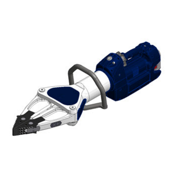
4.2 Unit in detail SP 333 E2 SP 555 E2 SP 777 E2 1 Star grip 2 Main switch 3 Quick exchange battery or power supply 4 Release button for battery and power supply 5 Handle 6 Ventilation slots 7 Spreader arms with plug-on tips 8 Plastic housing 9 Tool body 10 Protective cover 11 Light 12 Squeezing device 13 Protective plate for spreader arm 14 Yoke cover... -
Page 13: Hydraulic Circuit Diagram
4.3 Hydraulic circuit diagram To enable comprehension of the function, a simplified hydraulic ram of the rescue equipment (A) + hand valve (B) are depicted here. pulling / squeezing spreading 4.4 Operating movement controls The piston movement is controlled by the star grip on the attached valve (see illustration below). Star grip 5. Operation 5.1 Battery or power supply for eDRAULIC device Commissioning Before initial operation, the battery (where used) of the rescue device must be fully loaded, using the external charger. -
Page 14: Operating The Star Grip
Procedure: 1. Unplug the power supply (where used) from the mains. 2. Fully press down the two unlocking buttons and carefully pull the battery or power supply out of the device. Do not use force! Connection slot 3. The battery can now be recharged in the charger (please take note of the separate operating instructions for the charger and the batteries to be used); alternatively, the power supply can be replaced. 4. Insert the recharged or new battery into the eDRAULIC device until it reaches the stop. The battery or power supply will be automatically locked when correctly oper- ated. 5.2 Operating the star grip (also see chapter on "Operating movement control") Opening the device ( Turn the star grip in a clockwise direction (in the direction of the relevant symbol) and keep in this position. Closing the device ( Turn the star grip in an counterclockwise direction (in the direction of the relevant symbol) and keep in this position. "Dead-man’s" function: Following release, the star grip automatically returns to the central position, fully guaranteeing load retention. -
Page 15: Spreading, Pulling, Squeezing And Peeling
Worldwide safety guidelines pertaining to the specific country must be observed and complied with. In the Federal Republic of Germany, regular safety inspections according to the regulations of the Gesetzlichen Unfallversicherung (GUV; ‘Legal accident insurance’) are mandatory. WARNING / CAUTION / PLEASE NOTE! HURST eDRAULIC devices are not explosion-protected! When using the devices in potentially explosive environments, the following must be excluded: - that the device could trigger an explosion. - that working with the device could trigger an explosion; e.g. sparks may result from cutting an object. -
Page 16: Spreading
It is strictly prohibited to reach into the path of the rescue device (e.g. between the spreader arms and the material/object to which the force is to be applied)! CAUTION / PLEASE NOTE! The strong effect of the force of the rescue equipment during operation could cause pieces of the vehicle to break off or fly off, posing a danger to persons. -
Page 17: Pulling
Only work with the tips, small, tips slip off. Only so that the spreader for increasing the size is not damaged in the of a gap (not suitable area of the light metal for spreading) arms. 6.3 Pulling WARNING / CAUTION / PLEASE NOTE! The light metal alloy spreader arms may not be damaged. - HURST chain sets must be used for pulling. - When using a chain for pulling, make sure that the pins and hooks are positioned correctly so that the chain cannot slip. - Only chain sets in perfect condition may be used. - The pulling chains must be checked by an expert at least once a year. - Also consult the separate operating instructions for the corresponding chain set! Mounting bore for chain set... -
Page 18: Squeezing
The connecting pieces for HURST chain sets are fastened to the blades using load bolts in holes "A". (see illustration on the right) Permissible Chain sets: for SP 333 E2: KSV 11 for SP 555 E2: KSV 11 for SP 777 E2: KSV 11 NOTE: Also take note of all the instructions and regulations in the separately provided operating instructions for the chain sets. 6.4 Squeezing Squeezing is allowed - In the area of the tips. Squeezing... -
Page 19: Peeling
- With the special squeezing plates „A“ in the arms. 6.5 Peeling It is possible to peel sheet steel with the optional peeling tips of the spreader (max. panel thickness t, see chapter “Technical Data”). The spreader tip must be replaced with the peeling tip “A”, see 9.3.1 Tip changing. -
Page 20: Dismantling The Equipment / Deactivation Following Operation
WARNING / CAUTION! With particularly hard materials, chips may break out in an uncontrolled manner. Please maintain the safety distance! 7. Dismantling the equipment / deactivation following operation Once work has been completed, the device arms should be closed until the tips are only a few millimeters apart. This relieves the hydraulic and mechanical strain on the equipment. NOTE: Never store the eDRAULIC devices with fully closed arms! By fully closing the arms hydraulic and mechanical tension may develop in the device. Clean the rescue device after each operation and grease both the metallic and the mechanically movable parts. The lock of the spreader plug-on tips should also be greased from time to time. Greasing provides protection against excessive wear and tear or corrosion. Avoid storing the rescue equipment in a damp environment. -
Page 21: Maintenance And Service
Federal Republic of Germany, regular safety inspections according to the regulations of the Gesetzlichen Unfallversicherung (GUV; ‘Legal accident insurance’) are mandatory. ATTENTION! Clean off any dirt before checking the equipment! WARNING / CAUTION / PLEASE NOTE! To perform maintenance and repairs, personal safety equipment appropriate for the work is a mandatory requirement. The maintenance and repair staff must have adequate technical and specialized knowledge. HURST offers appropriate training courses for this. 8.1 Oil change Under normal working conditions routine oil changes are not necessary with eDRAULIC tools. The prerequisite is that: • the tools are always properly handled and stowed as per the applicable operating manual • the tools are tested on a regular basis as per our instructions on preventive maintenance • after 10 years service life an oil change is recommended Regular tests, oil change and/or repairs must be carried out by repair and maintenance personnel that is trained and authorized by the manufacturer. -
Page 22: Overview Of Edraulic Spreader
8.2 Overview of eDRAULIC spreader Inspections to be carried out: Visual Inspection Spreader • Opening width of arms at the tips (see chapter on "Technical Data"), • General tightness (leaks), • Operability of the star grip - check the automatic return into middle position after release (dead man’s function), • Existence and stability of handle, • Labels complete and legible, • Covers in perfect condition, • Spreader arms not cracked, • Pins and retaining rings on the spreader arms are present and in a proper condition, • Corrugation of the tips clean and well-edged, no tears. • The tips must be in place and locked • Illumination of main switch, work area and connection shaft fully functional. Battery and power supply • Casing undamaged • Electrical contact surfaces clean and undamaged • Cable undamaged... -
Page 23: Protective Equipment
8.3 Protective equipment Inspections to be carried out: • Check the protective equipment used on / in the vicinity of the rescue device. Pay particular attention to the protective cover for the movable parts (there may be no cracks!). 8.4 Checking the filter in the battery shaft The air suction filter is to be checked at least once a year or after use in a dusty environment. The filter can be checked from the outside if the mains unit (or battery) is removed (see illustrations below). If the filter is severely contaminated, it will need to be replaced. Procedure: Tilt the respective device as shown in the illustration. -
Page 24: Repairs
ATTENTION! Because HURST rescue devices are designed for highest performance, only components specified in the spare parts list for the appropriate equipment may be replaced. Other components in the device may only be replaced if: - You have participated in an appropriate HURST service training course. - You have been explicitly granted permission by HURST Customer Service (valid HURST certificate required!) ATTENTION! When cleaning units and equipment, note that no cleaning agent may be used that has a pH value outside the range 5 - 8! 9.2 Preventive service 9.2.1 Care instructions The outside of the device should be cleaned with a damp cloth from time to time (not the electrical contacts in the connection slot, on the battery and on the power supply). In... -
Page 25: Repairs
9.2.2 Function and load test If there is any doubt regarding the safety or reliability of a device, a function and stress test must also be performed. HURST offers appropriate test equipment for this. 9.3 Repairs 9.3.1 Replacing the plug-on tips Procedure: 1. In order to remove the plug-on tips “G”, you need to push the buttons “J” on both sides of a spreader arm completely and simultaneously and then remove the plug-on tip from the spreader arm by pulling it forwards. 2. Place the new tips onto the arm until they automatically click in place on the spreader arm. NOTE: Always replace both plug-on tips. When inserting the new tips, push both buttons “J” until the tip can be slid over them. After fitting, make sure that both buttons “J” are locked on each arm (that they are back in their original position). - Page 26 9.3.2 Replacing the handle 1. Close the rescue unit until a gap of only a few mm remains between the tips. Now switch off the device and remove the battery or unplug the power supply from the device. Clean the rescue equipment carefully. 2. Remove the fixing screws “A” and remove the top section of the handle “B”.
- Page 27 3. Remove the fixing screws “C” and remove the bottom section of the handle “D”. 4. Attachment of the handle takes place in the reverse sequence. NOTE: The torque required can be taken from the spare parts list of your particular unit.
- Page 28 9.3.3 Replacing the yoke cover 1. Remove the fixing screws “A” and remove the yoke cover “B”. yoke 2. Install the new cover.
- Page 29 9.3.4 Replacing the squeezing plates 1. Completely open the rescue equipment. Now switch off the device and remove the battery or unplug the power supply from the device. Clean the rescue equipment carefully. 2. Remove the fixing screws “A” and remove the squeezing plates “B”. squeezing plates 3. Install the new...
- Page 30 9.3.5 Replacing the protective plates 1. Close the rescue unit until a gap of only a few mm remains between the tips. Now switch off the device and remove the battery or unplug the power supply from the device. Clean the rescue equipment carefully. 2. Remove the fixing screws “A” and remove the protective plates “B”. protective 3. Install the new plates.
- Page 31 9.3.6 Replacing the protective covers 1. Remove the fixing screws “A” and remove the protective covers “B” using an appropriate tool. protective 2. Install the new covers.
-
Page 32: Troubleshooting
Spreader arms Battery fully Battery flat Charge battery move slowly charged? Battery defective Replace battery or jerkily when Air in the hydraulic Repair by an operated system authorized dealer, by personnel specially trained by HURST, or by HURST itself Power supply cable Power supply Reinsert power connected? not properly supply into the connected to the connection shaft. eDRAULIC device (not automatically locked). Power supply Reconnect external cable not properly power supply. connected to the external power supply. - Page 33 Solution Spreader arms do Battery fully Battery flat Charge battery not move when charged? Battery defective Replace battery operated. Power supply cable Power supply cable Replace power connected? defective supply cable Device defective Repair by an authorized dealer, by personnel specially trained by HURST, or by HURST itself Device doesn’t Device defective Repair by an perform at its given authorized dealer, by power personnel specially trained by HURST, or by HURST itself Following release, Casing damaged or Damage to the Repair by an the star grip star grip operation torsion spring for authorized dealer, doesn’t return to...
-
Page 34: Technical Data
Contact an authorised HURST dealer or the HURST Customer Service Department directly if the malfunctions cannot be rectified. The address for the HURST Customer Service department is: HURST JAWS OF LIFE, INC A Unit of IDEX Corporation 711 N. Post Road Shelby, NC 28150 USA Phone: (704) 487-6961 Fax: (704) 487-7271 e-mail: contacthurst@idex.com 11. Technical data Since all values are subject to tolerances, minor differences may occur between the data on your equipment and the data in the following tables. The values may also differ because of reading inaccuracies and/or tolerances in the measuring equipment used. -
Page 35: Edraulic Spreader
11.1 eDRAULIC spreader Device type SP 333 E2 SP 555 E2 Item number 271333000 271555000 [mm] 905 x 255 x 285 1002 x 265 x 280 Dimensions (excluding battery) L x W x H [in.] 35.6 x 10.0 x 11.2 39.4 x 10.4 x 11.0 Minimum spreading force [kN] (at a distance of 25 mm / [lbf.] 9442 11690 0.98 inches from the tips) [kN]... - Page 36 Device type SP 777 E2 Item number 271777000 [mm] 1075 x 308 x 285 Dimensions (excluding battery) L x W x H [in.] 42.3 x 12.1 x 11.2 Minimum spreading force [kN] (at a distance of 25 mm / [lbf.] 14160 0.98 inches from the tips) [kN] Max. possible spreading force * [lbf.] 134900 [kN] LSF spreading force (according to NFPA) [lbf.] 13260...
-
Page 37: Peeling
11.2 Peeling Device type SP 333 E2 SP 555 E2 SP 777 E2 [mm] Max. sheet steel thickness “t” [in.] 0.08 0.12 0.16 [mm] Max. possible opening [in.] 20.1 25.2 28.5 11.3 Noise emission (based on standard EN ISO 3744) SP 333 E2, SP 555 E2, Device type SP 777 E2... -
Page 38: Accessories
12. Accessories 12.1 Batteries Only HURST lithium-ion rechargeable NOTE: batteries may be used to operate Pay strict attention to the separate eDRAULIC devices. These guarantee Akku Power GmbH Safety Instructions for optimum performance and maximize the the batteries, a copy of which is available at operating time of the eDRAULIC devices. www.jawsoflife.com NOTE: Charging state To ensure maximum display operating time and maximum uptime, you must make sure that Query button the battery is always fully charged before connecting it to a rescue device. -
Page 39: Battery Charger
12.2 Battery charger Only the "eDRAULIC Power Pack Charger" may be used for the lithium-ion batteries. NOTE: Pay strict attention to the separate operating instructions for the battery charger. 12.3 Power supply The eDRAULIC devices have a specially developed power supply with which the devices can be directly connected to the power grid. The power supply converts the alternating current from the power grid into direct current, which means that it can be used instead of the battery. Mains plug Cable Adapter Cable Filter Structure: There is an adapter on one side of the power supply which can be simply inserted into the connection slot of the devices and locked. The other side has a mains plug. Both are connected by a cable. The mains plug is a Schuko plug with Protection Classification IP 68 or a US plug. The integrated filter is appropriate for the conversion of AC voltage to DC... -
Page 40: Chain Sets
12.4 Chain sets Chain sets are required in order to be able to perform pulling operations with the eDRAULIC spreader (see chapter, "Pulling"). Suitable chain sets: for SP 333 E2: KSV 11 for SP 555 E2: KSV 11 for SP 777 E2: KSV 11 13. Instructions regarding disposal Please duly dispose of all packaging materials and removed items. Electrical equipment, accessories and packaging should always be disposed of in an environmentally compatible way. Only for EU countries: Do not dispose of electrical equipment with your household waste! According to the European Directive 2002/96/EC governing electrical and electronic waste and their application in national legislation, old electrical equipment must be separately collected and recycled in an environmentally compatible manner. -
Page 41: Notes
14. Notes... - Page 44 Please duly dispose of all packaging materials and removed items. HURST JAWS OF LIFE, INC A Unit of IDEX Corporation 711 N. Post Road Shelby, NC 28150 USA Phone: (704) 487-6961 Fax: (704) 487-7271 e-mail: contacthurst@idexcorp.com Made in USA SP333E2_SP555E2_manual_271333085_en.indd © Copyright 2019 Hurst Jaws of Life, INC...
Need help?
Do you have a question about the eDRAULIC SP 333 E2 and is the answer not in the manual?
Questions and answers