Tascam US-224 Owner's Manual
Universal serial bus digital audio workstation controller
Hide thumbs
Also See for US-224:
- Use manual (4 pages) ,
- Installation notes (4 pages) ,
- Technical specifications (2 pages)
Table of Contents
Advertisement
Quick Links
Download this manual
See also:
Using Manual
Advertisement
Table of Contents
Troubleshooting

Related Manuals for Tascam US-224


Summary of Contents for Tascam US-224
- Page 1 TASCAM D000640100A TEAC Professional Division US-224 Universal Serial Bus Digital Audio Workstation Controller OWNER’S MANUAL...
-
Page 2: Important Safety Precautions
Important Safety Precautions CAUTION: TO REDUCE THE RISK OF ELECTRIC SHOCK, DO NOT REMOVE COVER (OR BACK). NO USER-SERVICEABLE PARTS INSIDE. REFER SERVICING TO QUALIFIED SERVICE PERSONNEL. The exclamation point within an equilateral triangle is intended to alert the user to the presence of important operating and maintenance (servicing) instructions in the literature accompanying the appliance. -
Page 3: Safety Instructions
SAFETY INSTRUCTIONS Read all of these Instructions. Save these Instructions for later use. Follow all Warnings and Instructions marked on the audio equipment. 1) Read instructions — All the safety and operating instructions should be read before the product is operated. 2) Retain instructions —... - Page 4 In case of such loss, TEAC Corporation will in no way be liable for any damages, consequential or otherwise, caused by such loss of data. Declaration of Conformity Model Number : US-224 Trade Name TASCAM Responsible Party : TEAC America, Inc 7733 Telegraph Road...
-
Page 5: Table Of Contents
3.3 Setting Up OMS (MacOS Only) ... 14 3.4 Tuning Your PC... 14 3.5 Notes on USB interfacing ... 16 4. Hooking up Audio and MIDI to the US-224 ... 17 4.1 Hooking up audio ... 17 4.2 Hooking up MIDI... 18 4.3 Using the Input Monitoring ... -
Page 6: Introduction
Introduction 1.1 Overview The US-224 is a USB controller designed for Cubasis and other Digital Audio Workstation (DAW) software applications. incorporates a two-input, two-output 24-bit audio interface, a 16-channel MIDI interface, and a control surface for your most-used mouse functions. -
Page 7: Controls And Indicators
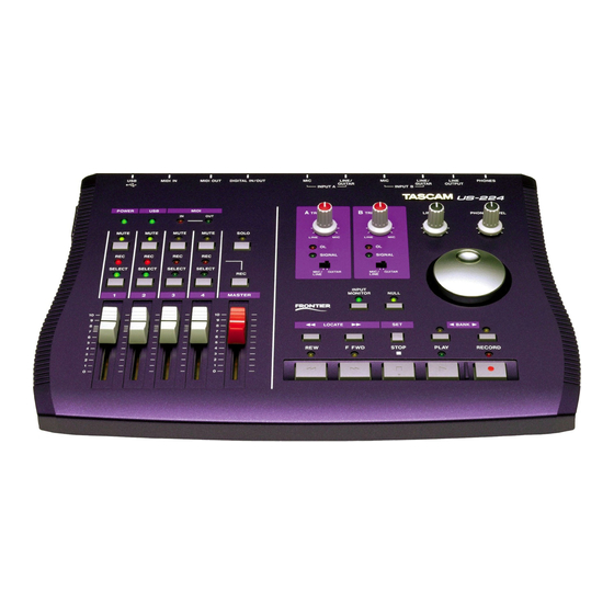
2. Controls and Indicators 2.1 Front Panel 1. Power LED 2. USB LED 3. MIDI In & Out LEDs 4. Mic/Line – Gtr Switches 5. Signal and OL LEDs 6. A and B Input Trims 7. Line Out and Phones Output Levels 8. -
Page 8: Rear Panel
2.2 Rear Panel 18. PHONES jack 19. OUTPUT L/R jacks 20. INPUT A and B 21. MIC INPUT A and B 22. Digital In and Out 23. MIDI Out 24. MIDI In 25. USB jack 26. POWER switch... -
Page 9: Front Panel Descriptions
224’s faders with those of the software application’s internal mixer. When using FADER NULL, the selected channel’s REC and SEL LED’s indicate the US-224’s fader position relative to the associated channel in Cubasis’ mixer. 10. Input Monitor Switch and LED toggles Input Monitor adjust mode. -
Page 10: Rear Panel Descriptions
14. Channel Faders send continuous controller information for banks of four faders, as selected by the BANK switch Master Fader controls level to the stereo bus output, and/or sends MIDI controller information to the host. 15. SELECT Switches selects channel for editing, recording, etc. SELECT LEDs indicates selected status of channel. -
Page 11: Installation
Consult application's manufacturer information.) NOTE: The US-224 is not supported under Windows 95. We also do not recommend Windows98 First Edition, due to its limited USB implementation. A fast EIDE hard disk is required for throughput of multiple audio tracks. -
Page 12: Installation
3.2 Installation Because the US-224 is a USB device, connection is pretty straightforward. Simply plug the USB cable into the US-224, and the other end into your computer. Make certain that your computer’s USB host port is enabled. (Normally, most standard PC BIOS settings default to enabled, but make certain that it hasn’t been turned off in... - Page 13 Click "Yes, I want to restart my computer", followed by the Finish button. The computer will reboot. Connect the US-224 to the computer, plug it in, and turn it on. The Windows plug-n-play will notice a new USB device and start the Add New Hardware wizard, which will find the needed files on its own.
-
Page 14: Macintosh
(The exception is Digital Performer, which utilizes FreeMIDI. The v3 drivers support independently.) To set up OMS to work with the US-224: First, run the OMS installer. If you do not have the current version of OMS, it freely downloaded www.opcode.com... - Page 15 PCI bus and allow for faster screen redraws. Special Note: optimizing your PC for audio, please refer to the PDF document PC_Optimization.pdf included on the US-224 CD-ROM. document is also available on the TASCAM website. computer’s While most digital...
-
Page 16: Notes On Usb Interfacing
While this is certainly a possibility, we recommend using as few other USB devices as possible in a system equipped with the US-224. The demands placed on the USB bus by passing multiple tracks of audio through it are considerable, and adding additional devices will risk reducing that bandwidth. -
Page 17: Hooking Up Audio And Midi To The Us-224
MIDI to the US-224 4.1 Hooking up audio To monitor output from your computer, connect the analog outputs of the US-224 to your mixer, amplifier or powered monitors. Output volume is controlled by the LINE OUT level pot. If you’ve got a digital mixer,... -
Page 18: Hooking Up Midi
MIDI I/O. Simply connect the MIDI out of your keyboard or other device to a MIDI in jack on the US-224, and vice versa. If you’ve got a MIDI sync box, you can use the MIDI I/O’s to send and receive MTC (MIDI Time Code). -
Page 19: Monitor Vs. Master Level
When using the US-224’s analog inputs, only the TRIM controls actually affect the input level to the audio software application. When using the US-224’s Digital inputs, the digital audio data received at the US-224’s digital input is passed directly to the audio... -
Page 20: The Us-224 Control Panel
The Input Monitor area is a viewable and controllable version of the US-224 INPUT MONITOR mixer. Here you can control the level and position of each US-224 input as it will appear on the LINE OUTPUT, DIGITAL OUT, and PHONES connectors. Three controls (level, pan and mute) are available for both inputs. -
Page 21: Buffer Size Adjustment
You can also control the input monitor settings that will be used when the US-224 first starts up. You can choose either the last settings in effect at the previous system shutdown, or any one of the four snapshots. 5.2 Buffer Size Adjustment The US-224 Control Panel contains a second page, tabbed “System”. - Page 22 The numbers below the tuning lights indicate how far out of tune the note is, in cents (100 cents is one semitone). When the note is in tune, the center ‘0’ light and both the Flat and Sharp arrows are bright green. Illustration 5.03 –...
-
Page 23: Interfacing With Your Audio Software
428 when in US-428 emulation mode, the full operational details of each individual program are beyond the scope of this manual. Details on using the US-224 in US- 428 emulation mode may be found in chapter eight. More specific information on... -
Page 24: Setting The Sample Rate And Bit Depth
Audio menu, and choose the US- 428 option (See illustration 6.03). You will also need to set the Input and Output devices to “US-224 Control Port” and the “Remote” setting should match the setting chosen in the US-224 Control Panel (see illustration 6.03). -
Page 25: Transport Controls And Locate Points
Illustration 6.07 - Record Enable 6.4 Transport Controls and Locate Points The transport controls on the US-224 are set up to directly correspond to the on- screen transport controls in Cubasis. So, for example, pressing PLAY on the US-224 will... -
Page 26: Mute/Solo
When changing to a different bank of faders, you may find that the fader on the US-224 is now out of position with the associated Pressing the FADER NULL button will disengage the US-224’s faders program, allowing you to move the US-224’s... - Page 27 To enable Direct Monitoring in Cubase VST, open the Audio Control Panel. In the “Monitoring” section of the window, check “ASIO Direct Monitor.” (You also need either “Record Enable Type” or “Tape Type” monitoring enabled.)
-
Page 28: A Sample Recording Session In Cubasis
Cubasis manual on the US-224 CD. You’ll find Windows and MacOS versions. 7.1 Setting Up Before starting Cubasis, make sure that the US-224 is turned ON, that its USB cable is connected to your computer’s USB port, and that the device has been initialized. -
Page 29: Recording Your Tracks
S/PDIF input. 7.2 Recording Your Tracks In Cubasis, choose the input(s) you wish to enable on the US-224. In the Audio menu, select Input, and click on the input pair on the US-224. The green Input icons will light in VST’s Input window for active inputs. -
Page 30: Mixdown
US-224. The selected channel will be highlighted below that channel’s fader on the screen. Moving the channel fader on the US-224 will adjust the relative volume of the selected channel in Cubasis. The corresponding fader on screen will update as you move the US-224’s fader. -
Page 31: Other Applications And Us-428 Emulation Mode
US-428 manual for details on setup and operation with that application. It’s also important to note that the US-224 is fully functional as a 16- and 24-bit audio interface and 16 channel MIDI interface with virtually all Windows and MacOS compatible applications. -
Page 32: Setting Up Sound Manager Support (For Use With Protools Free And Other Macos Applications)
US-224 outputs. When you click “Input” on the left, the available input devices appear on the right. Click on “US-224” to select it as the Sound Manager input device. Below it is “Input Source”: select A:B. - Page 33 “Volume” in this control panel is only used to enable or mute the US-224 output. Under “Sound In” you can select the “US- 224” instead of the Mac’s Built-in sources. You can also do this under the “US-224” control panel’s “System” tab. There you will find a field labeled “Sound Manager Input”.
-
Page 34: Technical Support
9. Technical Support 9.1 Troubleshooting When installing the US-224 for the first time, if you experience any unusual behavior, here are some things to check: Audio Drivers In Control Panel / System / Device Manager (Win98SE/ME) or Control Panel / System / Hardware / Device Manager (Win2000/XP), find the Audio control panel. -
Page 35: Troubleshooting Faqs
TASCAM website for the current version. Q. I don’t see the US-224 in Cubasis’ Audio Control Panel. A. Check to see if the US-224 is installed correctly within your OS. In Windows, go to the Device Manager (My Computer/Control Panel/Setup), and click on the Sound, video and Game controllers tab to make sure the US-224 is installed and operating correctly. -
Page 36: Appendix A - Midi Implementation Chart
Appendix A - MIDI Implementation Chart Function Basic Channel Default Changed Mode Default Messages Altered Note Number True Voice Velocity Note ON Note OFF After Touch Keys Channels Pitch Bender Control Change Program Change True # System Exclusive System Common :Song Pos :Song Sel :Tune... -
Page 37: Appendix B - Control Protocol
USB-based product. While the audio and MIDI I/O follow established which are easily interfaced with host applications, full integration of the control surface aspects of the US-224 requires a set of messages to be defined which permits two-way communication of control information between the host application and US-224. - Page 38 Transport/Locate command set The US-224 contains a set of standard transport switches: REW, FFWD, STOP, PLAY, and REC. In addition, dedicated status LED's are used to communicate the current transport state to the user. The LED's indicate REW, FFWD, PLAY, and REC. (Note that there is no LED to indicate STOP.) Additionally, there are three locate switches, which can be used to set and locate to...
- Page 39 Per-channel Control command set The US-224 includes a set of 4 channel-strip controls and LED's. Each channel-strip includes the following controls: a. linear fader for gain control b. Mute/Solo switch and LED c. Record-enable LED d. Select switch and LED Three modifier switches affect the channel strip indicators: a.
- Page 40 6. DUMP_FADER_POS: F0 4E<UNIT>12 10 <STRIP #> <STATE>F7 Bank-Switching Command Set The US-224 has two switches that allow the user to select the bank of application channels that is addressed by the four channel-strips. For example, an application with 32 virtual tracks would define eight banks of four channel strips each.
- Page 41 US-224 to Host Commands: DATA_WHEEL (identical to JL Cooper CS-10) a. BF 60 vv, vv = 2's complement using 7 data bits Host to US-224 Messages: UPDATE_ASN_LED: F0 4E<UNIT> 12 0F<STATE> F7 where <UNIT> Transmit as 0 for now. <STATE> is either 0x00 (LED OFF) or 0x7F (LED ON)
-
Page 42: Appendix C - Us-224 Technical Specifications
Appendix C - US-224 Technical Specifications General Frequency Response 20 Hz - 20KHz 1.0 dB / -3.0 dB LINE INPUT A/B to LINE OUTPUT TRIM min., +4 dBu input LINE OUTPUT level max. Noise Level Better than 92 dB A Weight MIC INPUT A/B to LINE OUTPUT TRIM min., 150 ohm terminated... - Page 43 DIGITAL IN Connector : RCA pin jack Format : IEC60958 Type2 Input impedance: 75 ohm Input Level : 0.5Vp-p DIGITAL OUT Connector : RCA pin jack Format : IEC60958 Type 2 Output Impedance: 75 ohm Output Level: 0.5Vp-p MIDI IN Connector : 5P DIN Format...
- Page 44 Ž US-224 Printed In Taiwan MA-0631...
Need help?
Do you have a question about the US-224 and is the answer not in the manual?
Questions and answers