Guardall V12AM - Security Sensor Installation Manual
- Installation instructions (2 pages)
Advertisement
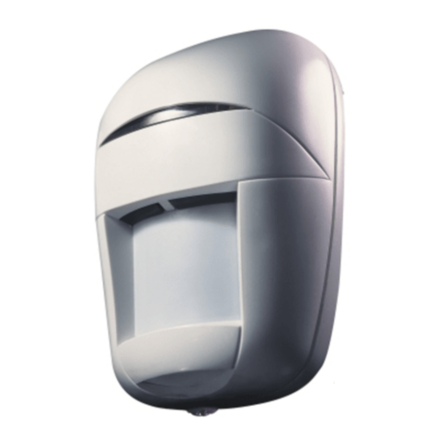
Overview

Connector Block

Note: If internal EOL resistors in use connect the loop to terminals 3 and 10
Switches
| No. | Function | FACTORY DEFAULTS |
| 1 | LED Enable |  |
| 2 | Pulse Count | |
| 3 | PIR Gain 1 | |
| 4 | PIR Gain 2 | |
| 5 | HS EOL1 | |
| 6 | HS EOL2 | |
| 7 | Mode | |
| 8 | AM Sensitivity | |
| 9 | AM On/Off | |
| 10 | Not Used |

Knockout Holes:
- Corner mounted
- Flush mounted
- Wall mounted using LPB2 brackets
For the off-the-wall tamper to be operational, screw must be fitted in either A* or B*
Coverage Diagrams

Initial Installation
The V12AM is designed to tolerate a wide range of environments, however, the normal professional installation guidelines should be followed:
- Avoid the main false alarm sources:
- Sunlight shining directly onto the detector,
- Heat sources within a zone,
- Strong air draughts onto the detector.
Mount the detector on a stable surface which is not subject to vibration. Large objects placed in front of the detector will cause significant changes in coverage.
- Preparation & Mounting
- Loosen the cover screw and remove the front cover. Grip the PCB at the connector block and pull forward while easing the retaining clips apart. Lift the module clear from the clips on the rear moulding.
- Decide on the mounting position and cable routing. The recommended mounting height is 2.3 m (7ft 6in). If required by the application, the detector can be mounted at other heights and the lens adjusted accordingly (see Checking V12AM Coverage section (d).
- Push out cable entry and appropriate mounting hole knock-outs (A for corner, B for flush mounting, C for low profile bracket).
- Fit the rear moulding to the wall.
- Wiring
- Run cables through the cable entry hole.
- Holding it by the connector block, fit the PCB into the rear moulding by inserting it into the lower retaining clips and clicking firmly into position.
- Connect the wires to the PCB terminal block.
- Guardall standard EOL resistors (8K2) can be enabled by setting switches 5 and 6 ON. For NEOL applications or operations with other resistor values, switch 5 and 6 OFF. Connect EOL loop between terminals 3 and 10 of the connector block.

- Do not re-fit front cover at this stage.

Pulse Count
The Pulse Count setting is factory enabled (switch 2 ON). The first detection will cause a short LED flash (if enabled, see section 5c). A second detection within 25 seconds is required to generate a unit alarm. If it is required that every detection generates a unit alarm then the Pulse Count setting should be disabled (switch 2 OFF).
PIR Gain
The Guardall V12AM is set for a detection area of 15m x 15m. To decrease the range to 10m x 10m BOTH switches 3 AND 4 must be moved to the 10m setting. The normal coverage instructions should also be followed.
Checking V12AM Coverage
Note that there will be a short delay (about 1 second) between movement and a unit alarm being generated while the V12AM validates the intruder signature.
Proceed with coverage checks as follows:
- Check the Anti-Mask is disabled (switch 9 OFF).
- Ensure that the voltage at terminals 1 and 2 is between 9 V and 16 V dc.
- Enable the LED by ensuring switch 1 is set ON (as supplied) or by taking the Test Input high. Note the Control Input must be low.
- Adjust the coverage: The declination of the zones can be adjusted vertically by loosening the main lens locking screws and moving the main lens. Declination of the zones is indicated on the module as follows:
- Main zones horizontal
- Normal position to give maximum range of 15m at 2.3 m (7ft 6in) mounting height.
- Main zones fully declined to give approximately 6 m (20ft) range at 2.3 m (7ft 6in) mounting height.
The horizontal coverage can be adjusted when corner mounted by loosening the wall mounting screws and adjusting the unit as required.
- Tighten main lens screws, then walk test the protected area checking that alarms are indicated at the control panel. Finally fit the front cover and tighten the cover screw if not using Anti-Mask.
Alarm Memory
This feature can be used provided switch 1 is OFF. Connect an output from the control panel to the V12AM Control Input with the following characteristics:
- System Set - Control Input High
- System Unset - Control Input Low.
Should an alarm occur when the system is set, the LED will not illuminate but the alarm will be memorised. When the system is subsequently unset, the LED will light constantly until the memory is reset. If the Test Input is high, the LED will not light continuously, but the detector can be walk tested normally without losing its alarm memory. Memory reset occurs the next time the system is set (Control Input High).
Note that the state of the Control Input also effects the operation of Anti-Mask and the unit's self diagnostic tests.
Anti-Mask (AM)
To enable the AM function of the V12AM set switch 9 ON.
AM sensitivity settings (switch 8):
- Standard sensitivity:
Switch 8 ON (as supplied) is suitable for most applications. - High sensitivity:
Switch 8 OFF is recommended for higher security applications.
Modes of operation (switch 7):
- Standard mode (switch 7 ON as supplied): The Auxiliary Output will be activated after 45 seconds of a continuous mask condition. The mask will be shown on the LED, if it is enabled. This can be reset by a unit alarm after 3 seconds provided the mask has been removed.
- High Security mode (switch 7 OFF): When a mask attempt is detected, both the Auxiliary Output and the Alarm Output will be activated and a mask will be shown on the LED (see section 9), if it is enabled. This can be reset after 15 seconds by a unit alarm, provided the mask has been removed and only if the Test Input is high or switch 1 is ON. Using this mode with switch 1 OFF provides a higher level of security as only a user with the appropriate control panel authorisation can reset Anti-Mask.
Note: These modes also vary the unit's response to various self diagnostic tests. It is strongly recommended that the Test Input is used and switch 1 set to OFF if High Security mode is selected. If the Control Input is connected, Anti-Mask is disabled when the system is set (Input high).
Refit the front cover and then generate an Anti- Mask calibration by one of the following:
- removing and re-applying power to the V12AM,
- taking the Control Input low from a previously high condition.
The Anti-Mask re-calibration takes 22 seconds and it is important to remain clear of the detector by a minimum of 2 metres during this time.
Diagnostics
Remote self test
This feature is only available in High Security mode (switch 7 OFF). Switch 1 must also be OFF and the Control Input low (system unset). To allow remote verification of the detector, a self test is initiated whenever the Test Input goes from high to low. If no problems are found, a unit alarm will be generated which the control panel can use to check the detector and also the wiring to the panel. If the detector fails self test, no unit alarm is generated.
Periodic self test
The detector regularly performs an internal electrical self test. If the self test detects a failure, the Auxiliary Output will be activated within an hour. In Standard mode (switch 7 ON) this condition will be reset by either a unit alarm or a successful periodic self test. In High Security mode (switch 7 OFF) only a successful remote self test will reset this condition.
Supply voltage monitor
The supply is continuously monitored. If it falls significantly below 9 Volts, the Auxiliary Output is activated and the LED will flash at 1Hz (once / second). In Standard mode (switch 7 ON) this condition will be reset if the supply voltage returns to greater than 9V dc. In High Security mode, the Test Input must also be taken from High to Low.
LED Indications
| Low Voltage | Flashing slow (1 Hz = once / sec). |
| Alarm | On for 3 seconds, if LED is enabled. |
| Alarm Memory | On continuously to indicate a memorised alarm (see section 6). |
| Mask | Flashing fast (4 Hz = 4 times / sec.) if LED is enabled. |
| Mask Circuit can not calibrate | Flashing alternatively fast (4 Hz) and slow (1 Hz) if LED enabled. |
These indications are disabled if Control Input is High.
Troubleshooting
No LED indication | Check LED Enable is selected, i.e. switch 1 ON or Test Input high and Control Input low. |
LED flashing slowly | Check supply voltage is greater than 9 V dc. |
| Continuous PIR activity Check for strong draughts indicated by LED activity | and other known constant alarm sources. |
Poor detection | Check lens adjustment. |
LED flashing fast or LED flashing fast / slow | Check carefully for mask. Check front cover is fitted correctly. Reset mask as described. |
| No indication on LED (when enabled), Auxiliary Output activated | Periodic self test fail; check connections and unit operation. |
Any further queries can be directed to the Guardall Technical Hotline: 0131 - 333 - 3802.
Accessories
LPB2 - a low profile bracket providing approximately
±45° horizontal and vertical adjustment (item no. W72321),
Corridor and curtain lens pack (item no. W73767).
Technical Specification
| Detector Voltage: | 9 V to 16 V dc. |
| Current: | 17 mA non-alarm, 18 mA alarm, typical at 12 V dc. |
| Max Ripple: | 2 V peak to peak at 12 V dc. |
| PIR Coverage Adjustment: | +3° to -11° vertically, ±5° horizontally when corner mounted. |
| LED Indication: | Internal switch or Test Input to enable. |
| Temperature Range: -10°C to +55°C (14°F to | 130°F). |
| Temperature compensation: | Increases gain only when room temperature close to body temperature. |
| Alarm Output: (NC ALARM) | Normally closed, voltage free, solid state relay contacts. Rated at 30 V dc, 50 mA with a maximum 10 Ohm on resistance. |
| Alarm Period: | Approximately 3 seconds. |
| Tamper Output: (NC TAMPER) | Normally closed, voltage free, switch contacts. Rated at 30 V dc, 50 mA. |
| Test Input (TEST): | Normally low or open circuit, connect to detector's positive supply to activate (High). Must have common ground with detector. |
| Control Input: (CTRL) | Normally low or open circuit, connect to detector's positive supply to activate (High). Must have common ground with detector. |
| Auxiliary Output: AUX) | Normally closed, voltage (NC free, solid state relay. Rated at 30 V dc, 50 mA with a maximum 10 Ω on resistance. |
Guardall Limited
Lochend Industrial Estate
Newbridge
Edinburgh EH28 8PL
Technical Hotline: 0131-333-3802
Website: www.guardall.co.uk

Documents / ResourcesDownload manual
Here you can download full pdf version of manual, it may contain additional safety instructions, warranty information, FCC rules, etc.
Download Guardall V12AM - Security Sensor Installation Manual
Advertisement


Need help?
Do you have a question about the V12AM and is the answer not in the manual?
Questions and answers