Advertisement
Quick Links
2
4
8
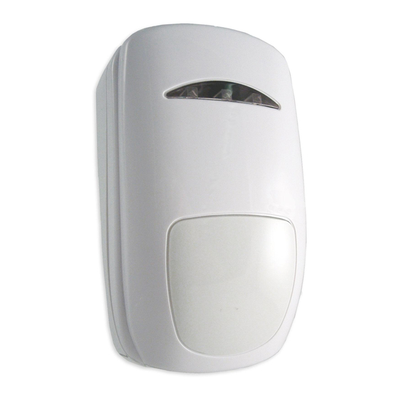
Diagram 1 - Description
1. Coin slot
2. Off the wall tamper (using this mounting hole
provides off the wall tamper)
3. Detector mounting holes
4. Cable entry knock-outs
5. Mirror adjustment and fi xing screw
6. Pyro Detector (Do not touch)
7. Microwave range control
8. Cover screw (Loosen only - do not remove)
Diagram 2 - Terminal block
10 9 8 7 6 5 4
NC
Ctrl
NC Aux
Tamper
1
3
5
6
7
3 2
+
Test
NC Alarm
12 V
Installation Instructions
Newbridge, Edinburgh EH28 8PL
Technical Hotline: 0131- 333-3802
Diagram 3 - Coverage Patterns
Volumetric Plan View 15m / 18m
7.5m/9m
0m
7.5m/9m
0
Volumetric Side View 15m / 18m
2.3m
0
4m/4.5m
1. Technical Specifi cation
Voltage:
Current:
Alarm, Aux &
Tamper:
Test Input:
Control Input:
Microwave range:
See datasheet for full information
Use in EN50131 Complaint Systems:
DTX 18 meets the requirements of TS50131-2-4:2004, Grade 3, Class II
1
with SW4 and SW9 ON and SW3 OFF.
DTX 15 meets the requirements of TS50131-2-4:2004, Grade 2, Class II
-
and is suitable for use on PD6662 Grade 3 systems with SW4 ON and
SW3 OFF.
DTX 15 / 18
Part No. 320902-0E
Guardall Limited
Lochend Industrial Estate
Website: www.guardall.com
4m/4.5m
7.5m/9m
12m/13.5m
7.5m/9m
12m/13.5m
12 V (9 V to 16 V dc)
Quiescent – 17 mA @ 12V
Max – 22 mA @12V (All LED's ON)
Normally closed (NC). Rated at 24 V dc, 50mA
Positive supply to enable LEDs and control
Remote Self Test
Positive supply for system Set. Otherwise
Unset
50% to 100% of range via potentiometer
15m/18m
15m/18m
Advertisement

Related Manuals for Guardall DTX 15


Summary of Contents for Guardall DTX 15
- Page 1 10 9 8 7 6 5 4 with SW4 and SW9 ON and SW3 OFF. DTX 15 meets the requirements of TS50131-2-4:2004, Grade 2, Class II and is suitable for use on PD6662 Grade 3 systems with SW4 ON and...
- Page 2 Faulty product should be returned to your supplier. (*1) To monitor Aux output on a separate zone fi t external EOL resistors. Note: Guardall recommend that the detector is regularly walk tested back to the (*2) Only Px/Qx V3.2 or above, with Fault EOL option enabled.
Need help?
Do you have a question about the DTX 15 and is the answer not in the manual?
Questions and answers