Guardall DTSx+ - Security Sensor Installation Manual
- Installation instructions (2 pages)
Advertisement
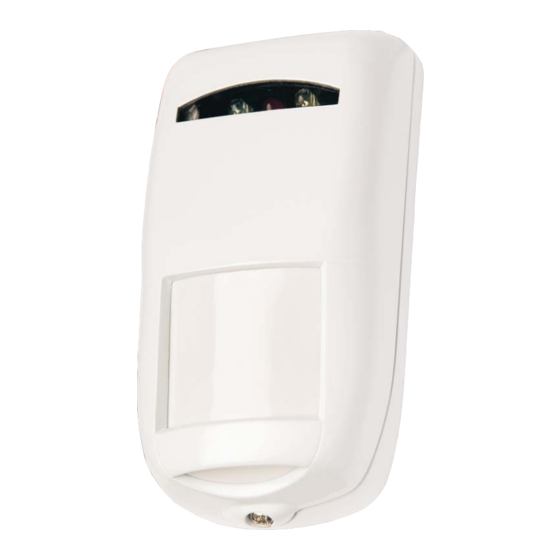
Unit Explanation

Off the wall tamper fitting is required for EN Grade 3 - the screw should be fitted in location A or C.
- Cover Screw (loosen only - do not remove)
- Microwave Range Control
- PCB Retaining Screw
- PIR Detector (do not touch)
- Cover Tamper
- Declination Indicator
- LEDs
- Off the Wall Tamper Connection
- Terminal Block
- Cable Knockout Positions
Terminal Block
 | | | | | | | | | |
| 1 | 2 | 3 | 4 | 5 | 6 | 7 | 8 | 9 | 10 |
| - 12 V+ | NC Alarm | Test | Ctrl | NC Aux | NC Tamper | ||||
Coverage Diagrams

Volumetric Plan View 15m

Volumetric Side View 15m
Technical Specification
| Voltage: | 12 V (9 V to 16 V dc) |
| Current: | Quiescent – 14 mA @ 12V Max – 30 mA @12V (All LEDs ON) |
| Alarm, Aux & Tamper: | Normally closed (NC). Rated at 24 V dc, 50mA |
| Test Input: | Positive supply to enable LEDs and control Remote Self Test |
| Control Input: | Positive supply for system Set. Otherwise Unset |
| Microwave range: | 50% to 100% of range via potentiometer |
See datasheet for full information
Use in EN50131 Compliant Systems
DTSx+15 meets the requirements of TS50131-2-4:2004, Grade 3, Class II with SW3 OFF, SW4 and SW5 ON. Coverage shown applies with unit mounted 2.3m high, SW2 OFF, microwave at max and PCB in position B. Changing these may affect approval compliance.
Declaration of Conformity:
Hereby Guardall Ltd, declares that DTSx+15/100 is approved for use in UK, Italy & Eire and is in compliance with the essential requirements and other relevant provisions of EU Directive 1999/5/EC.
Intended use: Within a building as an intruder detection device.
Safety Information: The power feed must be fused at 5A or less.
Installation Location
The recommended mounting height of the detector is 2.3m. Ensure the detector's fi eld of view is not obscured. Please refer to Installation Guidance Notes available on our website or call the Technical Hotline for further information.
Walk testing
Select switch 1 to ON.
The yellow LED displays PIR activity. The PIR coverage is adjusted by loosening the PCB retaining screw, moving the PCB up or down, then re-tightening the PCB screw. Position A=Horizontal, B=15m & C=8m.
The green LED displays microwave activity. Range is adjusted via the microwave range control (2 in diagram 1).
The microwave should be set to the minimum necessary to give the required coverage. Note that coverage under the unit may also change.
The red LED displays unit alarms.
Walk test the area checking that alarms are indicated at the control panel.
Check tamper operation if wired.
Operating Feature Selection

| FACTORY DEFAULTS | |
| No. | Function |
| 1 | LED Enable |
| 2 | Pulse Count |
| 3 | UW Day disable |
| 4 | AM / Faults O/P |
| 5 | AM Sensitivity |
| 6 | Anti-Stealth |
SW1: LED enable - See LED indications section.
SW2: Pulse Count
In harsh environments select switch 2 ON (pulse count).
SW3: Microwave Day Disable
OFF - the microwave will be permanently active.
ON - microwave is disabled when system Unset.
SW4: Anti-mask / Fault Output
| SW4 | Faults Signalled On | Mask Signalled On |
| ON | Aux + LED (if enabled) | Alarm + Aux + LED (if enabled) |
| OFF | LED | Aux + LED |
To reset a mask: Remove the mask, wait 30 secs, generate an alarm. If Switch 3 (UW day disable) is ON the Anti-mask is disabled.
SW5: Anti-Mask Sensitivity
In harsh environments, select switch 5 to OFF.
SW6: Anti-Stealth
SW6 ON - Enhances detection for high security applications.
Please refer to Installation Guidance Notes available on website or call the Technical Hotline for further information.
Remote Self Test (RST)
With switch 4 ON, an RST is generated when the TEST Input is taken high to low. The alarm output will signal a successful RST. A failure will generate a fault condition. This is only reset by a successful RST.
Alarm Memory
* System Set
Should an alarm occur the alarm will be memorised.
* System Unset and SW1 OFF
TEST Input Low: the red LED will remain ON (if an alarm is memorised).
TEST Input High: the LEDs display normally without losing alarm memory.
Memory reset occurs the next time the system is set.
LED Mode Setting
System Set: No LED indications
System Unset:
With SW4 OFF, the following table applies.
With SW4 ON, the following table applies except No Faults are displayed unless SW1 is ON or Test is High.
| SW1 | Test | Red | Green | Yellow | |||
| a | b | Fault | Other | Fault | Other | ||
| OFF | Low |  | - | | - | | - |
| ON | x | - | | | | | |
| x | High | - | | | | | |
x =don't care
LED Indications
Red LED Indications:
- Latched Alarm: ON constant.
Anti-Mask Fault: With latched alarm: Flicker...ON..Flicker..ON.. etc. ;
Anti-Mask Fault : No latched alarm: Flicker..OFF..Flicker..OFF.. etc.
Low Voltage: One Flash every second. - Low Voltage: One Flash every second.
Unit Alarm: ON for 3 secs.
Anti-Mask Fault : Flicker..OFF...Flicker..OFF..etc.
Green LED Indications:
Microwave Alarm: ON for 3 secs.
Microwave detection: One Flash.
Microwave Masked: 2.5 Flashes every second.
Microwave Fault: ON Dull (while Faulty).
Yellow LED Indications:
PIR Alarm: ON for 3 secs.
PIR Alarm event (pulse count only): One Flash.
PIR Masked: 2.5 Flashes every second.
PIR Fault : ON Dull (while Faulty)
Warranty
All Guardall products are warranted against defects in workmanship in materials (details available on request). In the interests of improving quality and design, Guardall reserve the right to amend specifi cations without giving prior notice. Faulty product should be returned to your supplier.
Note: Guardall recommend that the detector is regularly walk tested back to the control panel and that installers advise their customers to do this.

Documents / ResourcesDownload manual
Here you can download full pdf version of manual, it may contain additional safety instructions, warranty information, FCC rules, etc.
Download Guardall DTSx+ - Security Sensor Installation Manual
Advertisement


Need help?
Do you have a question about the DTSx+ and is the answer not in the manual?
Questions and answers