Advertisement
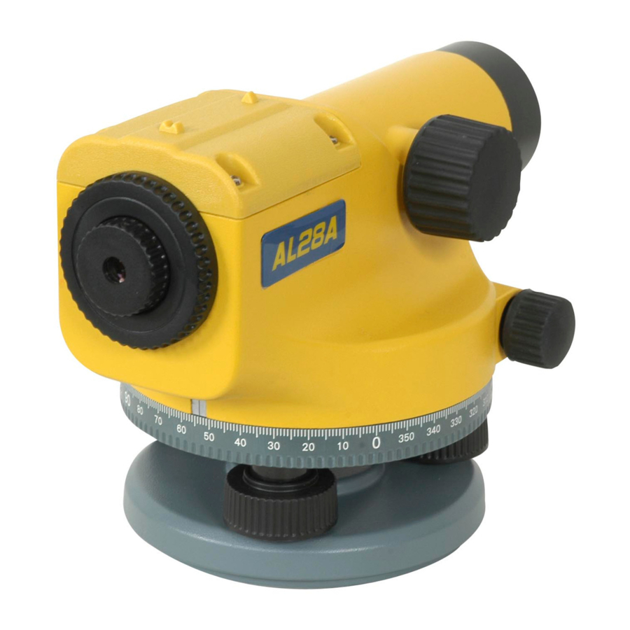
Features

- Focusing knob
- Sighting guide
- Crosshairs' adjustment screws (under cover)
- Crosshairs' focusing ring
- Eyepiece
- Horizontal rotation ring and angle index
- Leveling screws
- Base plate
- Circular level adjustment screws
- Horizontal tangent knob
- Circular level
- Mirror for reading circular level
- Objective
Maintenance and Care
- As with all precision instruments, the auto level should be transported and stored in its carrying case.
- When carrying the instrument mounted to a tripod, be sure to carry it vertically rather than over your shoulder.
- Whenever possible, store the instrument in a dry, shady area.
- Wipe the instrument clean with a cloth. Clean the objective and eyepieces with special care using a damp tissue or soft, clean, lint-free cotton cloth.
- When working in wet weather, wipe off the instrument and carrying case in the field and let them dry completely indoors with the case open.
Safety Information
Included in this manual are Cautions and Notes. Each of these words represents a level of danger or concern. A Caution indicates a hazard or unsafe practice that could result in minor injury or property damage. A Note indicates important information unrelated to safety.
How to Use the Instrument
Setting Up the Instrument
- Set up the tripod at a height appropriate for your use.
![warning]() Note: Make sure the tripod is stable and the tripod head is relatively level.
Note: Make sure the tripod is stable and the tripod head is relatively level. - Attach the instrument to the tripod.
- Level the instrument using the circular level as a reference.
- Focus the telescope crosshairs by turning the crosshairs' focusing ring.
Aligning the Instrument
- Align the telescope to the grade rod using the sighting guides.
- Turn the focusing knob to bring the grade rod into sharp focus. Precisely sight the center of the grade rod in the telescope crosshairs using the horizontal tangent knob.
- Check for parallax shift.
 Note: No parallax exists if the crosshairs and the grade rod graduations remain in coincidence even when you change your viewing angle (move your eye up/down and left/right in front of the eyepiece).
Note: After the bubble in the circular level has been centered, the compensator corrects residual line-of-sight inclinations. The compensator does not, however, eliminate any tilts resulting from inadequate adjustment of the circular level or line of sight. These must be checked regularly (see Adjusting the Instrument for more information).
Taking Measurements
Determining the Difference in Elevation

- Set up the instrument half way between two points (A and B).
- Take a reading at point A (a1 = 1.726 m) and another one at point B (b1 =1.259 m).
![warning]() Note: A slight deviation of the line of sight from horizontal will not cause any measuring error as long as the instrument is set up approximately half way between the two points.
Note: A slight deviation of the line of sight from horizontal will not cause any measuring error as long as the instrument is set up approximately half way between the two points. - Subtract b1 from a1 to get the difference between the points (d = 0.467 m).
![warning]() Note: Point B is 0.467 higher than point A because the difference is a positive number. If point B were lower than point A, the number would be negative.
Note: Point B is 0.467 higher than point A because the difference is a positive number. If point B were lower than point A, the number would be negative.
Establishing an Elevation
- Set up and level the instrument.
- Set the grade rod on a known elevation (30.55 m) and take a grade rod reading (1.72 m).
- Add the grade rod reading to the known elevation to get the height of instrument or HI (1.72 + 30.55 = 32.27 m).
- Subtract the elevation of the point you want to establish (31.02 m) from the HI (32.27) to calculate the difference between the two points (32.27 – 31.02 =1.25 m).
- Go to the point you want to establish and adjust the height of the grade rod until the calculated difference (1.25) is centered in the crosshairs.
Taking a Distance Measurement

Note: The instrument's stadia lines allow you to determine the distance between the instrument and the grade rod.
- Take readings at the upper stadia line (1.436 m) and the lower stadia line (1.152 m).
- Calculate the difference between the two readings (1.436 – 1.152 = 0.284 m).
- Multiply the difference by 100 to get the distance between the instrument and the grade rod (.284 x 100 = 28.4).
Computation Example
| Elevation | |
| Center Line Reading | 1.294 m |
| Distance Measurement | |
| Upper Stadia Line Reading | 1.436 m |
| Lower Stadia Line Reading | 1.152 m |
| Difference | 0.284 m |
| Distance (0.284 x 100) | 28. 4 m |
Taking an Angle Measurement
- Set up the tripod so that it is over a hub.
![warning]() Note: Make sure the tripod is stable and the tripod head is relatively level.
Note: Make sure the tripod is stable and the tripod head is relatively level. - Hang a plumb-bob from the plumb-bob hook on the tripod.
![warning]() Note: Make sure the plumb-bob is over the hub.
Note: Make sure the plumb-bob is over the hub. - Attach the instrument to the tripod.
- Center the plumb-bob over the pin in the hub by varying the length of the tripod legs or by shifting the instrument on the tripod.
- Accurately align the telescope to the first target using the sighting guides and a horizontal tangent knob.
![warning]() Note: The first target is a known point.
Note: The first target is a known point. - Set the horizontal rotation ring to 0.
- Accurately align the telescope to the second target and read the angle.
Adjusting the Instrument
Circular Level
- Set up the instrument.
- Center the bubble of the circular level using the leveling screws.
- Turn the telescope 180° (200 gon).
- Check to see whether the bubble is still centered in the circle. If it isn't, eliminate one half of the error with the leveling screws and the other half with the two adjustment screws for the circular level.
- Repeat the process until the bubble remains centered when the instrument is turned.
Line of Sight

- Set up the instrument half way between two points (A and B) that are 30 to 40 m apart.
- Take a reading at point A (a1 = 2.423 m) and another one at point B (b1 = 0.936 m).
- Subtract b1 from a1 to get the difference between the points (d = +1.487 m). Make sure you note whether value d is a positive or negative number.
![warning]() Note: Because the distance from the instrument to each of the points is equal, the difference in elevation is correct even if the line of sight is out of adjustment.
Note: Because the distance from the instrument to each of the points is equal, the difference in elevation is correct even if the line of sight is out of adjustment. - Move the instrument and reset it up so that it is about 2 m behind point B.
- Take another reading at point B (b2 = 1.462 m).
- Add b2 to d to get value c (1.462 + 1.487 = 2.949 m).
- Take another reading at point A (a2).
- Compare value c (2.949) to a2. If the line of sight is correct, both numbers should be the same. If they differ by more than 4 mm, reset the grade rod on point A and turn the crosshairs adjustment screws (unscrew the cover to expose them) until value c (2.949) is centered in the crosshairs.
![]()
The upper and lower adjustment screws are counter-screws and must not be set too tightly. - Repeat the process until the line of sight is correct (c and a2 are the same).

Specifications
| AL32A | AL28A | AL24A | AL28M | AL24M | AL20M | |
| Magnification | 32X | 28X | 24X | 28X | 24X | 20X |
| Dampening | Air | Air | Air | Magnetic | Magnetic | Magnetic |
| Accuracy* | +/-1.0mm | +/-1.5mm | +/-2.0mm | +/-1.5mm | +/-2.0mm | +/-2.5mm |
| Leveling Accuracy @ 50m | 0.5mm | 0.7mm | 1.2mm | 2.5mm | 2.5mm | 2.5mm |
| Telescope: | ||||||
| Aperture | 30mm (1.2 in.) | |||||
| Telescope image | Erect | |||||
| Field of view angle | 1⁰20' | |||||
| Shortest focus distance | 0.60m (1.97 ft.) | |||||
| Stadia constant | 100 | |||||
| Addition constant | 0 | |||||
| Dimensions (L x W x H): | ||||||
| Instrument | 103 x 190 x 135mm (5.2 x 7.5 x 5.3 in.) | |||||
| Case | 170 x 280 x 190mm (6.7 x 11 x 7.5 in.) | |||||
| Weight: | ||||||
| Instrument | 1.6 kg (3.5 lb) | |||||
| Case | 1.25kg (2.75 lb) | |||||
* Standard deviation according to DIN 18723 on 1 km of double leveling

Documents / Resources
References
Download manual
Here you can download full pdf version of manual, it may contain additional safety instructions, warranty information, FCC rules, etc.
Download Spectra AL28M, AL20M, AL24M, AL24A, AL28A, AL32A - Auto Level User Guide
Advertisement


Need help?
Do you have a question about the AL28M and is the answer not in the manual?
Questions and answers