Table of Contents
Advertisement
Quick Links
Advertisement
Table of Contents

Subscribe to Our Youtube Channel
Related Manuals for Spectra Precision UL633N


Summary of Contents for Spectra Precision UL633N
- Page 1 UL633N Hands-On training 11.07.17...
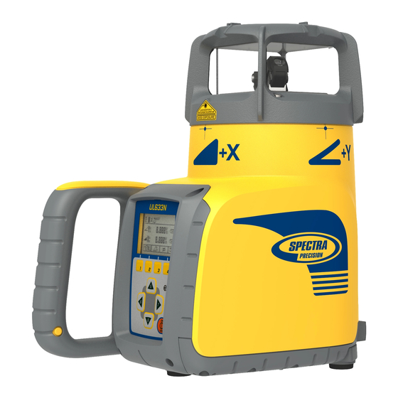
- Page 2 UL633N Components a - Keypad/LCD-Display b - Handle c - Rotor with fan beam lens d - Sunshade e - Axes Alignment Marks f - Sighting Guides/Scope Mounts g - Battery door h - Rubber Cover/Recharge Jack i - 5/8” x 11 Tripod Mounts...
- Page 3 Powering the UL633N 1 – UL is shipped with a rechargeable NiMH battery pack (Q104667), alkaline batteries can be used as a backup. 2 – The rechargeable battery pack can be charged inside as well as outside of the unit 3 –...
- Page 4 Powering the RC603N 1. Open the battery door using a coin or similar pry device to release the battery door tab on the RC603N. RC603N will be shipped with alkaline batteries. Rechargeable batteries can be used optional but need to be charged externally 2.
-
Page 5: Standard Display
Standard Display The remote control mirrors the functionality of the UL keypad. Battery status laser Battery Status Remote Control Mask selection Status Radio Connectivity Rotation speed/Scan angle HI alert function is activated Fan Beam is activated Button 1: Quickly press and release starts the MENU entry. -
Page 6: Turning On/Off The Laser
Turning On/Off the Laser Turning On/Off the laser Press the power button to turn On/Off the laser. – Depending on the setup (horizontal or vertical) and if a grade value has been dialed in, the unit starts the temperature/reference check while the thermometer symbol is flashing. –... -
Page 7: Standard Features
Standard Features X-Y-Z-grade entering Standard Display Step and Go mode Quickly press and release button 2 starts the grade entering mode. Both grade values will be shown. Press/release button 1 grade reverse Y Press/release button 2 grade reverse X Press/release button 3 ... - Page 8 Standard Features Standard Display X-Y-Z-grade entering Digit Select mode Quickly press and release button 2 starts the grade entering mode. Both grade values will be shown. Press/release button 1 quick set to 0% Press/release button 2 change the sign of the grade value Press/release button 3 ...
-
Page 9: Using The Rotation Mode
Standard Features Using the Rotation mode Repeatedly pressing the button 4 toggles through 0, 80, 200, 600, rpm regardless if the unit is in automatic or manual mode. At 0 rpm, the beam stops automatically close to the +Y- axis center position. In automatic mode, using buttons 5/8 increases/decreases rotor speed from 0 to 80 and then up to continuously in 10 rpm increments. -
Page 10: Manual Mode
Standard Features Manual mode Pressing and releasing button 3 at the Standard Display activates/deactivates the manual mode regardless if set up horizontal or vertical. Manual mode is indicated by horizontal lines next to the axes symbols. An additional bubble helps to adjust the laser on the cross axis when set up vertical. -
Page 11: Special Menu Features
Special MENU Features Menu Functions (Radio controlled) Press and release button 1 at the Standard Display to enter the MENU. The menu offers always only the features which can be selected depending on the setup (horizontal or vertical). The selected icon will be highlighted. A down arrow at the the right site indicates that the user can scroll down through the menu using the button 8 (down arrow). - Page 12 Special MENU Features Menu Functions (IR controlled) If the RC603N is paired with a transmitter and the radio connection doesn’t work, e.g., through a pipe, the IR connection offers the following functions. Press and release the MENU button 1 at the Standard Display. Pressing and releasing button 3 changes the unit always back to the standard or previous display.
-
Page 13: Automatic Planelok Mode
Automatic PlaneLok mode The PlaneLok mode can be activated in horizontal and vertical automatic and manual mode. In PlaneLok mode when set up horizontal, the beam will be locked to a fixed elevation point (up to (490 ft) located on one or both axes at each side of the laser. - Page 14 Automatic PlaneLok mode Note: When used in vertical mode, the receiver has to be placed with the photocell on the bottom side. display shows a flashing –PL– during the time the laser is searching and adjusting the beam to the HL760 on-grade position.
- Page 15 Steep Slope using PlaneLok Set up the UL633N at the bottom part of the steep slope area using the slope bracket (M402 laser tilting base). Check the laser beam elevation and place the two receivers at the desired hubs.
- Page 16 Steep Slope using PlaneLok Select PlaneLok at the menu and start Dual Axis PlaneLok by pressing button 4. The transmitter starts searching for both receivers and locks the beam at the on-grade position. 10/16/2017...
- Page 17 Automatic Grade Match mode The Grade Match mode can be activated in horizontal automatic and manual mode. In Grade Match mode, the laser can be used to measure the existing grade value between two known elevation points (up to (490 ft) located on one or both axes at each side of the laser 1.
- Page 18 Manual Grade Match mode In Manual Grade Match, the beam on both axes can be adjusted to desired positions (Indoors) or to the receiver‘s on-grade position , e.g, when other receivers as the HL760 are used. 1. Press and release the MENU button at the Standard Display and select Grade Match. 2.
- Page 19 Automatic Axis Alignment mode Automatic Axis Alignment mode adjusts automatically the direction the grade axis is pointing to the receiver’s location by an electronically simulation of rotating the unit on its base to match the hub. Using Axis Alignment, the laser axes can be aligned to one or two direction hubs (up to (490 ft) located on one or both axes at each...
- Page 20 Automatic Axis Angle Measurement View Axis Angle Measuring the angle between to existing direction points in a range up to max. +/-40° can be done performing two axis alignments in sequence, e.g., on the Y-axis. The angle measurement range goes up to 80 degrees with an accuracy of 0.5°. 1.
-
Page 21: Mask Mode
Mask Mode / Standby Mask mode Select the Mask icon and press and release button 4 to open the Mask setting menu. Depending on which side or corner the beam should be turned off, the required sector can be selected. Press and release the buttons 5 to 8 for moving a short flashing line around the mask mode symbol. - Page 22 Reference Check/Rotor Centering Start Reference Check When working during temperature changes and over long distances the product requires a frequent reference check to maintain accuracy. The transmitter will do reference check on a regular basis. When carrying out work where accuracy is paramount it is advised to manually prompt a reference check. Press and release the MENU button at the Standard display and select Reference Check.
- Page 23 Info Press and release the MENU button at the Standard Display and select Info Buttons 6/7 can be used to toggle between UL, RC and Runtime Press and release button 4 to confirm the selection. The UL/RC information (software version, ID, etc.) or the runtime of the UL will be displayed. Additional detailed RC information is available using the RC603 menu :...
- Page 24 Service Press and release the MENU button at the Standard Display and select Service. Buttons 6/7 can be used to toggle between Calibration Y and Calibration X OR Calibration Z when set up vertically. Press and release button 4 to confirm the selection. The calibration at the selected axis starts the field calibration procedure.
- Page 25 Special Features – Using SF601 Manual Spot Search mode The Spot Search mode is used for layout applications by detecting the plumb beam manually using the Spot Finder SF601 and can be activated in horizontal and vertical automatic and manual mode. Press and release the MENU button 1 at the Standard Display and select Spot Search.
- Page 26 Special Features - Vertical Setup Z-Axis Automatic Spot Align The Spot Finder SF601 guides the plumb beam to the target point in the horizontal axis, while the Z-axis grade value will be maintained. Using Spot Alignment, the plumb beam can be aligned automatically to one direction hub (up to 80 m (260 ft) located in front of the plumb beam.
- Page 27 Special Features - Vertical Setup Z-axis Automatic SpotLok Automatic SpotLok (like PlaneLok) can be used to align and hold the plumb beam automatically to the SF601’s center point continuously adjusting the Z- and X- axis until exiting this mode. The UL looks always to the center position of the SF601 and re-adjust the beam immediately to the center to avoid any setup/alignment drift caused by vibrations or temperature influences (e.g.
- Page 28 Special Features - Vertical Setup Z-axis Automatic Spot Match Automatic-Spot-Match can be used for measuring an unknown grade value between two existing elevations e. g., an open trench with an unknown grade value. The plumb beam will be automatically aligned to the SF601 center point (Z- and X- axis) and switches back to automatic Z-axis grade mode while displaying the measured Z-grade value.
- Page 29 Special Features - Vertical Setup Line Scan Line Scan centers the rotor horizontally and can be used to align the plumb beam to a desired horizontal position. Press and release the MENU button 1 at the Standard Display and select Line Scan. Pressing and releasing button 4 activates the Line Scan mode while the rotor checks the limits of the X- axis and stops at the center position.
-
Page 30: Setting Menu
Position Info On/Off When in Settings, press and release button 4 at the UL633N to open the Pairing menu. The display shows the currently paired units (up to two receivers and two remote controls). 2. If already 2 remote controls have been paired, one of them has to be deleted using button 1 (CLR). - Page 31 Press and release the Audio button (B) – display shows PAIR. Press the Units button again – the display shows PAIR and a rotating bar. After completing PAIR, OK will be displayed. The UL633N pairs now automatically with the new receiver. Press and release the HL760 Power button two times to exit the menu.
-
Page 32: Grade Entry
Setting Menu Grade Entry Select the Grade Entry icon and press and release button 4 to open the Grade Entry menu. Buttons 6/7 can be used to toggle between Step and Go and Digit Select. Press and release button 4 to confirm the selection. Grade Display Select the Grade Display icon and press and release button 4 to open the Grade Display menu. - Page 33 Setting Menu Sensitivity Selection Select the Sensitivity icon and press and release button 4 to open the Sensitivity menu. The desired sensitivity: Low, Mid (Default) and High) can be selected using the buttons 6/7. Press and release button 4 to confirm the selected Sensitivity.
- Page 34 Setting Menu Set Password Select the Set Password icon and press and release button 4 to open the Password menu. Use button 1 to 8 to type in a password containing of 4 digits and repeat the password at the second row. Press and release button 4 to store the selected password;...
-
Page 35: Select Language
Setting Menu Select Language Select the Language icon and press and release button 4 to open the Language menu. Use button 5 to 8 to select the required local language (EN, DE, IT, FR, ES, PT, NL, DA, NO, SV, FI, PL, TR, CZ). -
Page 36: Error Messages
Error Messages Any error message can be deleted with a short press of button 4 (OK). The table shows the related description and possible solutions. The next service center should be contacted if a different error message as shown at the table will be displayed. Error Description Solution... - Page 37 SF601 - User Guide SF601 attached to a grade rod using the standard receiver clamp SF601 attached to the optional pipe laser target base...
- Page 38 SF601 - Components 1 - SF601 2 - Slider 3 - Center Hole 4 - Power Button 5 - Bubble Vial 6 - Battery LED 7 - Mode LED 8 - Red Direction LEDs 9 - IR transmitters/receivers 10 - Marking notches (front and back) 11 - M6 Clamp Mount 12 - Battery door 13 - Latch for Battery Door...
- Page 39 SF601 – Powering/Features and Functions Powering the SF601 1. Open the battery door pulling the battery door latch. The SF601will be shipped with alkaline batteries. Rechargeable batteries can be used optional but need to be charged externally 2. Insert four AA batteries noting the plus (+) and minus (-) diagrams inside on the battery door. 3.
- Page 40 UL633N turns off the fan beam automatically. Note: With a quick press and release of the SF601 power button, the fan beam lens at the UL633N will be activated/deactivated while a previous activated auto mode will be exited.
- Page 41 SF601 – Manual/Display Mode With a quick press and release of the SF601 power button, the fan beam lens at the UL633N will be activated/deactivated while a previous activated automatic mode will be exited. Manual/Display (Spot Search) mode: If the fan beam lens will be activated and no automatic mode has been started, the SF601 is in manual/display mode where the RED direction LEDs guide the user to the center position of the fan beam.
- Page 42 Sun Shield + SF601 Mount w/ Rubber Strap Q104865 Spot Finder Adaptor incl. Rubber Strap Pins for Rubber strap Q104864 Sun Shield for longer range when the SF601 is used in bright sunlight...
- Page 43 Q104865 Mount: SF601 Tripod Setup Tripod thread centered with the SF601 and tripod mounting threads...
- Page 44 Q104865 Mount: SF601 Batter Board Setup Clamp thread for attaching the receiver clamp Marking notch aligned with the center of the nail...
- Page 45 Q104865 Mount: SF601 Free Standing Setup Marking notches on both sites...
Need help?
Do you have a question about the UL633N and is the answer not in the manual?
Questions and answers