Advertisement
Introduction
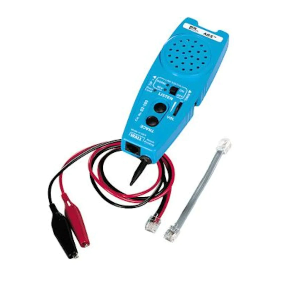
The IDEAL ABS™ Tester (Almost a Butt Set) is a simple to use tester for basic troubleshooting of analog voice system installations. It monitors phone lines for dial tone quality and presence of power, tests for correct jack polarity (detects reversed tip and ring), and indicates call addressing for correct telephone extensions.

ABS™ Tester
- Simple to use for basic troubleshooting of communication systems.
- Used for diagnostic work involved with analog voice system installation and maintenance.
- Will receive and reproduce telephone system dial tone for the purpose of determining the quality of the tone. (LISTEN function or OFF hook)
- Checks tip and ring jack polarity.
- Identifies presence of power. (AC and DC)
- Indicates call addressing for correct telephone extensions.
- Equipped for jack and cross-connect system access.
- Receives tracing signals for identifying specific conductors in a cable run. (TRACE function requires separate tone.)
- Volume control to adjust test tones.
- Clip lead access for two center pins of RJ11 jack.
- 60 cycle noise rejection for clear tone detection
- Lanyard attachment point for hands free operation
- Drop resistant, moisture resistant case and speaker for long life durability.
- Replaceable line cord assembly to maximize life of tester
- Comes complete with 9 volt battery installed in tester
- Pocket sized

If OVERLOAD LED (Red) is illuminated and warning tone sounds, the telephone line being tested is a digital line. Toggle off the LISTEN button or remove the tester from the line within 30 seconds to avoid damage to the tester.
Instructions for Use
To Monitor for Dial Tone Quality at a Modular Jack
- Plug the ABS™ Tester into a phone system jack using a jumper cable (supplied with ABS™ Tester).
- Turn Line Status switch to ON position.
- The Line Status LEDs will show if the line under test has DC power and if it is wired correctly with a Green NORM LED
- Push the LISTEN button, taking the line "off" hook and hear the dial tone.
- Listen for good clean dial tone.
- Push LISTEN again to end test.
(Note: The LISTEN feature can be toggled on and left on without draining the battery. Some digital systems can be listened to depending on the digital system being tested.)
To Monitor Dial Tone at a Cross Connect
- Plug modular plug on clip jumper (supplied with ABS™Tester) into ABS™ Tester jack.
- Use clips to connect to appropriate contacts on cross connect terminals.
- Push the LISTEN button, taking the line "off" hook and hear the dial tone.
- Listen for good clean dial tone.
- Push LISTEN again to end test.
(Note: The LISTEN feature can be toggled on and left on without draining the battery. Some digital systems can be listened to depending on the digital system being tested.)
To Detect Tracing Tone Signal
- Push TRACE button and the probe end becomes active.
- Hold TRACE to trace a line within a bundle of cables or to "tone out" a line on a punch down block.
To Detect Tracing Tone Signal at Wall Outlet
- Plug the ABS™ into a wall outlet using a jumper cable (supplied with ABS™).
- Push TRACE to hear tone if the line to that wall outlet has been activated with a signal from another source such as IDEAL ABS™ Signal Thrower™ #62-184 or IDEAL PathFinder™ #62-080.
Test for Line Status
- Plug the ABS™ Tester into a wall outlet using a jumper cable.
Test Results
- Green NORM lights when the communication line under test is powered up and the TIP pin/wire is positive with respect to the RING pin/wire and the phone is "on-hook".
- Red REV indicator will light if TIP an RING polarity are reversed.
- Both NORM and REV LEDs will be illuminated if an AC voltage is present.
- Both NORM and REV LEDs will flash if the line is ringing (for phone number verification).
Clip Lead Access
- Attach alligator clips from butt set, tone generator, or other test equipment to large perforated test pads allow secure for access to the two center pins of an RJ11 jack.
- The LINE STATUS switch can be in ON or OFF position when using test pads.
Note: In the OFF position a 10K load is removed from the test terminal to the RJ11 interface circuit.
Accessory Part
K-8343 Cable Assembly, RJ11/Alligator clips
K-7919 RJ11/RJ11 Cable Assembly
Battery Replacement
- Remove screws from back of case using a #1 Phillips screwdriver. Carefully open tester.
- Remove old battery.
- Install new battery (9 volt battery).
- Close tester and replace screws. Do not over tighten.
Warranty limited solely to repair or replacement; no warranty of merchantability, fitness for a particular purpose or consequential damages.
IDEAL INDUSTRIES, INC.
Sycamore, IL 60178, U.S.A.
800-304-3578 Customer Assistance
800-947-3614 DataComm Assistance
www.idealindustries.com
ND 1000-4 Made in U.S.A.

Documents / Resources
References
Download manual
Here you can download full pdf version of manual, it may contain additional safety instructions, warranty information, FCC rules, etc.
Advertisement


Need help?
Do you have a question about the ABS and is the answer not in the manual?
Questions and answers