
Related Manuals for IDEAL SIGNALTEK


Summary of Contents for IDEAL SIGNALTEK
- Page 1 SIGNALTEK Cable Performance Tester Operation Manual Rev B. JAN 07 IDEAL INDUSTRIES Inc.
- Page 3 INDUSTRIES, Inc. The information in this document is not to be used or duplicated in any manner without prior written approval from IDEAL INDUSTRIES. IDEAL INDUSTRIES and the IDEAL INDUSTRIES logo are registered trademarks of IDEAL INDUSTRIES. All other product names mentioned in this book are trademarked or copyrighted by their respective manufacturers.
- Page 4 (except batteries and cable adapters), which in IDEAL INDUSTRIES’ sole opinion proves to be defective within the scope of the Warranty. In the event IDEAL INDUSTRIES is not able to modify, repair or replace nonconforming defective parts or components to a condition as...
- Page 5 The Warranty described above is Buyer’s sole and exclusive remedy and no other warranty, whether written or oral, expressed or implied by statute or course of dealing shall apply. IDEAL INDUSTRIES specifically disclaims the implied warranties of merchantability and fitness for a particular purpose. No statement,...
-
Page 6: Table Of Contents
1 Introduction ................1-1 Cable Qualification Testing ............1-1 SIGNALTEK Test Functions ............ 1-3 Cable Types ................1-4 Cable types that can be tested with SIGNALTEK: ....1-6 Test Port and Cable Adapters..........1-6 Standard Accessories .............. 1-6 Optional Accessories..............1-7 Memory.................. - Page 7 Fiber Qualification Abilities ............6-2 Setup and Calibration............... 6-4 7 Troubleshooting & Frequently Asked Questions....7-1 8 Care and Calibration..............8-1 9 Specifications................9-1 10 Customer Service ..............10-1 IDEAL INDUSTRIES World Wide Contact Information ..10-2 SIGNALTEK Operation Manual...
-
Page 8: Table Of Figures
Figure 4-1 Autotest Tab ..............4-1 Figure 5-1 Wire map Results ............5-1 Figure 5-2 Link Establishment Results......... 5-3 Figure 5-3 Cable Performance Results ........5-4 Figure 6-1 SIGNALTEK-FO Top Connectors....... 6-2 Figure 6-2 LC-to-SC cable............6-3 Figure 6-3 SC Coupler..............6-3 IDEAL INDUSTRIES, Inc. - Page 9 Figure 6-4 Calibration Setup............6-4 Figure 6-5 Calibration Complete Screen ........6-5 Figure 6-6 Fiber Link Establishment..........6-5 SIGNALTEK Operation Manual...
-
Page 11: Introduction
SIGNALTEK is easy to use. It offers any installer the ability to perform cable performance tests and rapidly locate connectivity issues. - Page 12 RS-488, RS-232, and many more. However, it is often the case that in any residential or commercial network, Ethernet devices will be the only type used. SIGNALTEK uses the IEEE 802.3ab (Gigabit Ethernet) standard as a reference for cable performance testing. Rather than a traditional certification test where frequency-based parameters...
-
Page 13: Signaltek Test Functions
PC, switch, router or other device and the opposite end of the link is connected to the SIGNALTEK handset. Wire map – Displays the physical paring of the cable. Also... -
Page 14: Cable Types
IP subnet, and the name of the internet service provider (ISP). Ping – Displays the results of the ping test when SIGNALTEK is connected to an active Ethernet network. The user can choose the target IP address to ping, the packet size, the number of packets to send, the delay between packets, and the failure threshold. -
Page 15: Figure 1-1 T-568 A/B Color Code
1000Mbps Tx + Bi-Dir A + Tx - Bi-Dir A - Rx + Bi-Dir B + Unused Bi-Dir C + Unused Bi-Dir C - Rx - Bi-Dir B - Unused Bi-Dir D + Unused Bi-Dir D - SIGNALTEK Operation Manual... -
Page 16: Cable Types That Can Be Tested With Signaltek
CAT 6 UTP CAT 6 STP RG59 CAT 6a UTP Test Port and Cable Adapters SIGNALTEK is configured to allow testing of the following interfaces: RJ45, 4 pair UTP/STP RJ12, 3 pair UTP Telephone wire Coaxial Connector Type “F” Standard Accessories... -
Page 17: Optional Accessories
120-240 volt AC power adapter with multi national plugs (Part Number 4010-00-0136) Memory SIGNALTEK test records are stored internally in the display unit and can be copied to a USB memory drive. Internal memory capacity is approximately 20,000 records. External memory capacity is limited only by the size of the USB memory drive. - Page 18 CAT 6 UTP CAT6a UTP CAT 5 STP CAT 5e STP CAT 6 STP CAT 6a STP CAT 7 STP Phone CAT 3 - 3 pair 10/100 CAT 3 - 4 pair Coax RG 59/6 Misc. 2-Wire IDEAL INDUSTRIES, Inc.
-
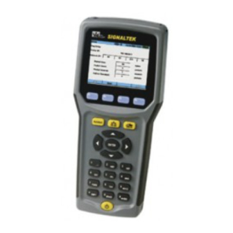
Page 19: Figure 1-2 Signaltek Handsets
Figure 1-2 SIGNALTEK Handsets The following table describes the function of each button and LED on the SIGNALTEK handsets. SIGNALTEK Operation Manual... - Page 20 The directional keypad and Enter keys are used to navigate around the SIGNALTEK user interface. When the tab color is yellow, the left and right arrow keys are used to move between the tabs. Pressing up or down scrolls through the options within each tab.
- Page 21 The # key also functions as Escape to return to the previous screen. The power button turns SIGNALTEK on and off and also controls the backlight brightness. To turn on, press and release the button. To turn the power off, press and HOLD the button until the screen turns off, then release.
-
Page 22: Batteries & Power
Batteries & Power Each SIGNALTEK handset is powered by four AA batteries. Alkaline batteries are included. User supplied NiMH or NiCd rechargeable batteries may be used in either handset. The optional AC-DC power supply may be used to power the handsets for extended periods of time. -
Page 23: Figure 1-3 Battery Discharge Characteristics
Once the indicator turns red the pack is nearly completely discharged and the tester will turn off very shortly because of the discharged battery pack. Figure 1-3 Battery Discharge Characteristics Alkaline NiMH Time SIGNALTEK Operation Manual 1-13... -
Page 24: Battery Charging Warnings
Battery Charging Warnings The DC power input port is not designed to charge batteries that are installed in SIGNALTEK. However, it is possible that a component failure may cause the unit to charge batteries causing the batteries to rupture, damaging the SIGNALTEK or causing personal injury. -
Page 25: Graphical User Interface Navigation
Graphical User Interface Navigation When turned on, SIGNALTEK will display the firmware version number then boot up to the AutoTest tab. This section of the manual will describe the various screens and the information displayed in each screen. There are four primary display screens in the SIGNALTEK graphical user interface. -
Page 26: User Interface Navigation
User Interface Navigation Figure 1-4 AutoTest Tab - Active Active Job (1) Function Tabs (2) Link Status (3) Date/Time (4) Battery Status (5) IDEAL INDUSTRIES, Inc. 1-16... -
Page 27: Figure 1-5 Autotest Tab - Inactive
Then press ENTER to activate or modify a selection. There are several options for user selectable fields: Open a Window – Pressing ENTER on certain fields such as the Job names or Setup options will open a new window. SIGNALTEK Operation Manual 1-17... - Page 28 ENTER to select it. Select/Deselect Options – Where there is an option to select or deselect an option, highlight the field with the up/down arrows and press ENTER to place or remove the checkmark. IDEAL INDUSTRIES, Inc. 1-18...
-
Page 29: Setup And Configuration
Selecting either 568 A or B makes diagnosing wire map problems easier because the color of the conductor is correctly represented in the SIGNALTEK display. Universal Service Order Code (USOC) is used when testing three- pair cables for voice applications. In this configuration the pairing... -
Page 30: Autotest Preferences
The Autotest Preferences screen determines which tests are run in any one of three line conditions: Remote, Link, and No-Link. SIGNALTEK continuously scans the line and when the Autotest button is pressed, it runs the selected tests as defined from the Preferences screen. -
Page 31: Autotest Modes
Autotest Modes SIGNALTEK will perform an Autotest in one of three link conditions: Remote – The SIGNALTEK display and remote handsets are connected to a single cabling link. All cable performance tests can be performed. Link – The SIGNALTEK display handset detects an active LAN link. -
Page 32: Cable Performance Setup
The Cable Performance Setup screen controls the test time and the pass/fail threshold for the bit error rate tests. There are four different bit error rate tests that can be run on SIGNALTEK. Cable Performance – This is the standard test that complies with the IEEE 802.3 specification for Gigabit Ethernet links. -
Page 33: Figure 2-7 Cable Performance Setup
IEEE 802.3 specification. Choosing the custom option allows a value for the failure threshold to be set manually, overriding the failure threshold calculated by IEEE 802.3. SIGNALTEK Operation Manual... -
Page 34: Ip Address Setup
IT department. A manual IP address can be configured if desired. One reason to manually set the IP address is to use the SIGNALTEK handset as a target to ping. For example if the cabling and server equipment is... -
Page 35: Ping Setup
The DHCP test can be run from either the Autotest or Manual tab. View the DHCP results to see the IP address assigned to SIGNALTEK as well as the IP addresses of the DHCP Server and Network Router Ping Setup SIGNALTEK can be configured to ping a network device as part of the Active Link test. -
Page 36: Device Defaults
70% of the speed of light. This setting is used to calculate the correct length measurement with the TDR. Typical settings for NVP are 0.68 for non-plenum (PVC jacketed) cable and 0.72-0.75 for plenum rated cable. The correct setting for IDEAL INDUSTRIES, Inc. -
Page 37: Owner Information
The Owner Information screen is where the personal data about the SIGNALTEK owner/operator is entered. This data is stored for each job and is saved/printed on the header of the SIGNALTEK cable performance reports. If this information is left blank, the accompanying header information on the printed reports will also be blank. -
Page 38: Timeout Options
The Timeout Options screen is used to set the time that the display backlight and handset stay on during periods of inactivity. Entering “0” prevents the display or handset for automatically turning off. Figure 2-13 Timeout Options IDEAL INDUSTRIES, Inc. 2-10... -
Page 39: Measurement Units
The tester includes a real-time clock to mark the date and time of each Autotest. When the batteries are removed the internal clock will operate for approximately 24 hours, after which the date and time will need to be reset. Figure 2-15 Date and Time SIGNALTEK Operation Manual 2-11... -
Page 40: Cable Id Prefix
The new Cable ID prefix will now appear in the Autotest tab and can be used on any future test. Names can also be deleted from the Cable ID Prefix list by highlighting the name and pressing the F4 (Delete) key. Figure 2-16 Cable ID Prefix Setup IDEAL INDUSTRIES, Inc. 2-12... -
Page 41: Language
Language SIGNALTEK can support a variety of languages. To change the language, choose an option from the pull-down list and press Enter. For the new language to take effect the tester must be turned off and back on. Figure 2-17 Language Setup... -
Page 42: Updating Firmware
RJ45 patch cord. If necessary, the display handset will update the firmware on the remote handset via the RJ45 port. With SIGNALTEK powered off, insert the drive into the USB port. Turn on SIGNALTEK and watch for the message that indicates a firmware update is in progress. - Page 43 USB drive after updating the tester. However, if you are updating several SIGNALTEK testers, you can simply take use the same USB drive to update all the testers then delete the file when finished. Note: Do not remove the USB drive while an update is in progress.
-
Page 45: Test Storage And Management
Press the “Add” function key to create a new job. At a minimum, the Company Name must be filled in since this becomes the job name. All other fields are optional. However, most of the information here is printed on the header of the IDEAL INDUSTRIES Inc. -
Page 46: Printing And Copying To Usb Drives
50%. Printing and Copying to USB Drives SIGNALTEK test files are created in a format called XML (Extensible Markup Language). This is a more powerful version of HTML which is used to code internet pages for viewing with a web... -
Page 47: Direct Pc Connection (Windows Xp™ Only)
Highlight the desired job. Press the “Copy to USB” function key to copy the job file to the USB drive. The job file and a file called “SIGNALTEK.xsl” will be copied to the USB drive. The XSL file is called a “style-sheet” and instructs the web browser how to display the test file. -
Page 48: Printing Directly To A Usb Printer
Linux native PCL driver included in SIGNALTEK. To print a job to a compatible printer, connect the printer to SIGNALTEK’s top USB port. A USB “A to B” cable is required for direct printing. These cables are available at any electronics or computer store. -
Page 49: Running Autotests
Figure 4-1 Autotest Tab The Autotest list will automatically update as the link status changes. When testing with the SIGNALTEK remote the link status icon will change to green when the remote has been detected. Pressing the Autotest button before the remote is detected (red link icon) the no-link test will run, only checking the wire map and length. -
Page 50: Beginning An Autotest
There are three modes of autotest operation; Remote, Link, and No-Link. Details of each operation mode are described on page 2- Connect each of the SIGNALTEK handsets to the link to be tested. Qualification testing is performed with both SIGNALTEK handsets. -
Page 51: Stopping An Autotest
SIGNALTEK will request an IP address from the network. Successful negotiation of an IP address indicates that SIGNALTEK is able to communicate on the network and that the cabling can support IP traffic. Ping Test – Used to send packets to a device on the network to check its response. -
Page 52: No-Link Testing
No-Link Testing SIGNALTEK can perform a basic wire map and length test on un- terminated cables. This is called no-link testing and is indicated by the red link indicator at the top of the display. The red link indicator... -
Page 53: Test Results
Test Results There are three categories of tests results that SIGNALTEK will display: wire map/length, Bit Error Rate, and active network. This chapter will explain the results of each type of test. Wire map Results The wire map screen displays the results of the pair test as detected by the Gigabit Ethernet chip-set. -
Page 54: Wire Map Testing Active Lan Links
10/100Mbps Ethernet switches internally short the unused pairs (4/5, 7/8) since they are not used at these speeds. In this case, SIGNALTEK will detect the shorted pairs at the switch. This is not a cabling problem; the tester is simply detecting the internal short on the switch. -
Page 55: Bit Error Rate Tests
The result from the Link Establishment test indicates the type of device to which SIGNALTEK is connected. MDI means that SIGNALTEK is connected to a PC while MDIX means that it is connected to a hub or switch. Figure 5-2 Link Establishment Results... -
Page 56: Figure 5-3 Cable Performance Results
Figure 5-3 Cable Performance Results The results screens for the Cable Performance, VoIP, Web and IP Video tests all display the following information: Results – Indicates Pass or Fail. Fails when the number of errored packets is greater than the number specified in the Setup options for that test type. -
Page 57: Performance Test Failures
Another factor affecting the SNR is the temperature of the cable: as the temperature increases, so does the attenuation of the cable. Accordingly, in very hot locations, links at 100m or less in length may still exhibit SIGNALTEK Operation Manual... - Page 58 excessive attenuation. Increased attenuation will reduce the SNR of the link and lead to bit errors. Test Results...
-
Page 59: Fiber Optic Testing
Fiber Optic Testing Overview SIGNALTEK is available with a fiber optic testing option. The SIGNALTEK-FO has incorporates additional hardware to support fiber optic testing via Small Form Factor (SFP) modules. These modules are commonly used in high-performance network switches to provide high-speed backbone links over long distances and have been incorporated into SIGNALTEK-FO to provide a low cost method of qualifying fiber optic links. -
Page 60: Fiber Qualification Abilities
Fiber Qualification Abilities When qualifying fiber optic cabling, SIGNALTEK-FO operates in a manner very similar to the standard SIGNALTEK. The tester will run cable performance tests to qualify a link as being able to support Gigabit Ethernet at an acceptable bit error rate and will perform a link establishment test to verify link speed and measure the attenuation of the link. -
Page 61: Figure 6-2 Lc-To-Sc Cable
The LEDs also serve as a polarity indicator. When connected to a link with the correct polarity, both the red and green LEDs on each handset will be lit. If only one of the LEDs is lit when connected to a SIGNALTEK Operation Manual... -
Page 62: Setup And Calibration
1. Choose FIBER from the cable type pull down menu to put the SIGNALTEK into the fiber test mode. Connect the LC- SC patch cord to each handset and use the provided SC coupler to join the two patch cords. - Page 63 (RX), and the computed loss value in micro watts and decibels (Loss). Note: The fiber optic modules will only link at 1000Mbps. They will not drop to 100 or 10Mbps on low quality links as the copper test will. SIGNALTEK Operation Manual...
-
Page 65: Troubleshooting & Frequently Asked Questions
(and possibly other brand) switches will detect this pulse and temporarily de-activate the port. When this happens SIGNALTEK will be unable to request an IP address and the DHCP and Ping tests will fail. To prevent this from occurring, go to SIGNALTEK’s Autotest Preferences screen and de-select the Wire map test. - Page 66 What type of testing is available on coax and non-data cables? Coax cables can only be tested for length and wire map (open/short/terminated) because only one physical pair (center conductor and shield) is present. At least two pairs are required to perform an Ethernet cable performance test.
- Page 67 Monitoring can only be done on a link with the SIGNALTEK handsets attached to both ends of the link. There is no ability to connect to an active network and perform bit error tests. To what standard does SIGNALTEK test? The IEEE 802.3x standard is the international specification for...
- Page 68 Gigabit applications. SIGNALTEK’s active LAN features can also be used to diagnose cabling or network problems that may not be cable related. The link establishment, DHCP and ping functions are three of the most common software tools used to troubleshoot networks.
- Page 69 If all tests pass, connect the SIGNALTEK directly to the user’s PC with a patch cord and go to the Manual test tab. Highlight Link Establishment and press F1.
- Page 70 Yes. See page 3-3 for details. Will I get email notifications about firmware upgrades? Yes. If you register SIGNALTEK by mailing in the registration card or through IDEAL’s website you will be notified as soon as firmware upgrades are available.
- Page 71 Are multiple remotes available? Since SIGNALTEK is an active Gigabit Ethernet bit error rate tester, inexpensive passive remotes are not available as they would not be able to support the level of testing required to qualify cabling to IEEE 802.3 standards.
-
Page 73: Care And Calibration
2% per day. This means that after one month a fully charged set of NiMH batteries will only have 40% of their capacity remaining. Calibration SIGNALTEK does not require calibration and does not contain any user-serviceable or adjustable components. All service and repair IDEAL INDUSTRIES Inc. - Page 74 IDEAL INDUSTRIES service center. Opening the SIGNALTEK housing or defacing the access seal voids the product warranty. Registration Owners are encouraged to register the instrument immediately upon purchase. Registered owner contact information is used to notify owners about new firmware or other product updates.
-
Page 75: Specifications
Mini-USB “A” device port Standard USB “B” host port DC power input for long term BERT monitoring Test Standards Qualification/BERT – IEEE 802.3 standard for Gigabit Ethernet link performance Wire map- EIA/TIA 568-B pairing. 568 A/B color code display options IDEAL INDUSTRIES Inc. - Page 76 Internal Memory 64MB Secure Digital card 32MB Linux partition (operating system) 32MB FAT partition (user storage area) USB Device Support USB 1.2 and 2.0 flash memory drives (thumb drives) up to 1GB capacity USB printers that support generic PCL drivers (many HP Deskjet, Laserjet, and Officejet models) Physical Dimensions Display Handset: 7.9”L ×...
-
Page 77: Customer Service
Canada, call IDEAL INDUSTRIES at 1-800-435-0705 or 1-800- 854-2708. Service in the USA Before returning a unit for service, call IDEAL INDUSTRIES Technical Support at 1-800-854-2708. When returning a unit for service: 1. Include customer name, company, address, telephone number, proof of purchase (for warranty repairs), and a description of the service required. -
Page 78: Ideal Industries World Wide Contact Information
Canada, call your local distributor. Before returning a unit for service outside the U.S.A., contact your local distributor or one of the IDEAL INDUSTRIES Corporation offices listed below. If your local distributor does not have a service facility, they will provide assistance in returning the tester to an authorized IDEAL INDUSTRIES service facility. - Page 79 IDEAL INDUSTRIES (U.K.) Limited 225 Europa Boulevard Gemini Business Park, Warrington Cheshire WA5 7TN, England Telephone+44 (0) 1925 444446 Fax+44 (0) 1925 445501 E-Mail:Ideal_UK@idealindustries.com IDEAL INDUSTRIES GmbH Gutenbergstr. 10 85737 Ismaning GERMANY Telephone +49-89-99686-0 Fax +49-89-99686-111 E-Mail: Ideal_Germany@idealindustries.com IDEAL INDUSTRIES AUSTRALIA...
- Page 80 IDEAL INDUSTRIES CHINA L.L.C Unit 505, Tower W1, The Towers, Oriental Plaza No. 1 East Chang An Avenue, Dong Cheng District Beijing, 100738, China Telephone 86-10-8518-3141 86-10-8518-3142 Fax 86-10-8518-3143 E-Mail: Ideal_China@idealindustries.com IDEAL INDUSTRIES BRASIL LTDA. América Business Park Av. Marginal do Rio Pinheiros, 5200 - 201/F 05693-000 - São Paulo - SP Brasil...
- Page 81 Manual Part No. 6510-91-0003 Rev. B IDEAL INDUSTRIES Inc.