
Related Manuals for Ametek Gemco 952CP Ram-Set


Summary of Contents for Ametek Gemco 952CP Ram-Set
- Page 1 (217) 352-9330 | Click HERE Find the Ametek / Gemco 952CP at our website:...
- Page 2 Gemco 1996 Ram-Set Automatic Press Shut Height Controller Installation and Maintenance Manual Gemco 1996 Ram-Set Automatic Press Shut Height Controller...
- Page 3 Preface This manual provides a system description, installation, maintenance and trouble shooting instructions for the Gemco 1996 Ram-Set automatic shut height controller. Copyright 2001 by AMETEK Automation & Process Technologies All Rights Reserved -- Made in the USA Version 1.0...
-
Page 4: Table Of Contents
Contents Chapter 1: General Description 1.1 Controller Features and Functions 1.2 Output Board Features and Functions Chapter 2: Installation Instructions 2.1 Introduction 2.2 Mechanical Installation 2.3 Electrical Installation Chapter 3: Programming and Operating Instructions 3.1 RS-485 Protocol Information Chapter 4: Maintenance and Trouble Shooting Chapter 5: Programming and Function Charts Chapter 6: Transducer Connector Pin Out Chart Wiring Diagrams... -
Page 5: Chapter 1: General Description
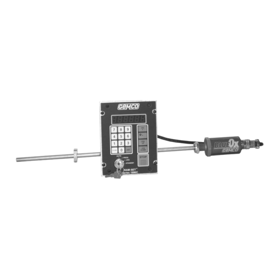
Chapter 1: General Description The standard 1996 Ram-Set consists of a transducer, transducer cable termination kit, controller, and output module. The transducer device is a magnetostrictive linear displacement transducer (LDT for short). The LDT consists of a fi xed guide tube assembly attached to an electronics package, and a non-contacting magnet assembly that moves up and down the guide tube. -
Page 6: Output Board Features And Functions
Chapter 1: General Description Located on the rear of the unit is a (14) fourteen terminal connector which interfaces with the output module, provides the 115VAC input, and also provides four auxiliary outputs. A (6) six terminal connector for transducer input and a D9 connector for RS485 communication are also located on the rear of the unit. -
Page 7: Chapter 2: Installation Instructions
Chapter 2: Installation Instructions Introduction This section describes the installation and wiring of a standard Ram-Set controller, output module and transducer. Changes to these instructions should be made as necessary if special options and/or equipment are used. The controller and output module should be installed in an area free of water spray, corrosive gases, fl ying chips or other foreign matter. -
Page 8: Electrical Installation
Chapter 2: Installation Instructions 3. Mount the supplied junction box to the crown of the press in an area free from obstruction. The fl exible cable from the junction box runs through the elbow assembly to the transducer. Run conduit from the junction box to the controller. Note: Transducer wires only in this conduit. A maximum transducer cable length of 30 ft. - Page 9 Chapter 2: Installation Instructions 3. This unit has been set up to work in inches or millimeters. The operator can select between working with inches (to 1/1000 of an inch) or millimeters (to 1/100 of a millimeter). 0 or 1 0 = Millimeter 1 = Inch Default is inch mode (1).
- Page 10 Chapter 2: Installation Instructions 6. Press Type: Select the type of press: (if applicable) 0, 1 or 2 0 = single action (standard) 1 = double action (inner slide) 2 = double action (outer slide) Note: If option 1 or 2 is picked, the 110VAC from the slide gap switch must be connected to Ram-Set per Wiring Diagram E-0204800-C.
-
Page 11: Chapter 3: Programming And Operating Instructions
Chapter 2: Installation Instructions 12. Drift Window: Establish an acceptable drift window. If the slide moves outside of this window, the In Position relay denergizes. Typically 0.010 to 0.020 inch. Value Note: In any cases where F - 3 - 9 - 1 - ENT is used, steps one (1) through eleven (11) will be erased from memory and will have to be repeated. - Page 12 Chapter 3: Programming and Operating Instructions 4. Clear All Die #’s and Positions: This function lets you clear all die numbers and shut height values without affecting the other functions. Simply select “PROG” mode and depress: F - 7 - 5 - 3 - ENT. This will remove all die numbers and position values.
- Page 13 Chapter 3: Programming and Operating Instructions Once the die number is selected and <ENT> has been depressed, the preprogrammed counter balance value and shut height value for that die # will be displayed to be verifi ed. Depressing <ENT> again will confi rm and enable a drive to the selected shut height and the counter balance for that die will be implemented.
- Page 14 Chapter 3: Programming and Operating Instructions Example: To enter die number 1 and shut height of 10.000: STXZmmF1ED1E0000EEOT. To access data through the serial port, the ENQ ($05) character must proceed entries. Example: STXZmmENQF1ED1EEOT would cause the Ram-Set to return STXZbbACKF001D001 : 10000EOT. If commands are strung together in the same transmission, ENQ must precede each function that data is being requested from: Command Symbols...
- Page 15 Chapter 4: Maintenance and Trouble Shooting The following procedures are intended as an aid to isolate system malfunctions down to fi eld replaceable elements. These ele- ments include; controller, output module, transducer and interconnecting wiring. Preliminary Checks Check System connections at the transducer, junction box, controller and output module to ensure that all connectors and wires are secure.
- Page 16 Installation and Maintenance Manual...
- Page 17 Chapter 4: Maintenance and Trouble Shooting Outputs will not operate or continuously stay on. Problem: Output interface wire(s) disconnected, output driver blown, CPU problem or blown fuse on output module. Check all Cause: wire connections and output fuse. If check out proceed as follows: To check up and down relays put keyswitch in jog mode.
- Page 18 Chapter 4: Maintenance and Trouble Shooting Note: Malfunctions due to the above can usually be cleared by removing, and then reconnecting power to the control- ler. The cause of such problems can be determined and eliminated. If removal and reconnection of power does not correct the problem, a controller failure has occurred.
- Page 19 1080 North Crooks Road • Clawson, MI 48017 800-635-0289 • 248-435-0700 • 248-435-8120 www.ametekapt.com • www.ametek.com 1996.M1R 03/02 • Z150...
Need help?
Do you have a question about the Gemco 952CP Ram-Set and is the answer not in the manual?
Questions and answers