Table of Contents
Advertisement
Quick Links
PF1 SCR Series
60-1200 Amperes
Single-phase
Phase-fired
SCR POWER CONTROLLER
Instruction, Operation and
Maintenance Manual
Number: 9100032
Revision 3
530 La keview Pl aza Blvd, Ste C
Worthington, O hio, USA 43085
To l l F r e e : 1 - 8 8 8 - P W R - C N T L ( 7 9 7 - 2 6 8 5 )
P h o n e : 6 1 4 - 3 0 8 - 5 5 0 0
F a x : 6 1 4 - 3 0 8 - 5 5 0 6
We b :
w w w. h d r p o w e r. c o m
Advertisement
Table of Contents

Related Manuals for Ametek PF1 SCR Series


Summary of Contents for Ametek PF1 SCR Series
- Page 1 PF1 SCR Series 60-1200 Amperes Single-phase Phase-fired SCR POWER CONTROLLER Instruction, Operation and Maintenance Manual Number: 9100032 Revision 3 530 La keview Pl aza Blvd, Ste C Worthington, O hio, USA 43085 To l l F r e e : 1 - 8 8 8 - P W R - C N T L ( 7 9 7 - 2 6 8 5 )
- Page 2 Revision 2 July 2015 Revised Address Revision 3 August 2022 General Revision 2022 by Ametek HDR Power Systems. No portion of this document may be reproduced either mechanically or electronically without the prior consent of Ametek HDR Power Systems...
- Page 3 Option CR/OC (Current Regulation/Over Current Trip) Option PR Option VIPR CHAPTER 6 - THEORY............................21 Functional Description Overview of the PF1 Digital Firing Control Circuit Pulse-Train Firing Phase-Lock Loop SPAN and ZERO Controls Voltage-Squared Feedback Rev 3 Ametek HDR Power Systems...
- Page 4 Appendix A – System Schematic Appendix B – 60-225 A Outline Appendix C – 350-500 A Outline Appendix D – 650 A Outline Appendix E – 800-1200 A Outline Appendix F – Declaration of Conformity Ametek HDR Power Systems Rev 3...
-
Page 5: Table Of Contents
Table 5.1 VIPR Regulation Switch Settings ....................19 Table 7.1 Troubleshooting Chart (Symptoms and Solutions) ..............25 Table 7.2 Torque Specifications ........................25 Table 8.1 PF1 Spare Parts List ........................27 Table 8.2 PF1 Drawing List ..........................28 Rev 3 Ametek HDR Power Systems... - Page 6 Table of Contents PF1 SCR Power Controller Ametek HDR Power Systems Rev 3...
- Page 7 The SCR Power Controller makes use of components dangerous for the environment (electronic printed circuit boards, electronic components). The components removed must be taken to specialized collection and disposal centers. E151547 IEC 947-5-1 100kA SCCR Rev 3 Ametek HDR Power Systems...
- Page 8 Safety Instructions PF1 SCR Power Controller Ametek HDR Power Systems Rev 3...
-
Page 9: Table 1.1 Pf1 Model Number Breakdown
800 A rms - 800 Lug Kit (>225 A) - LG 1000 A rms - 1000 Can have multiple selections 1200 A rms - 1200 NOTE: N.O. Thermostat is included in current ratings above 60 A. Rev 3 Ametek HDR Power Systems... -
Page 10: Table 1.2 General Specifications Of Pf1 Models
** If you will be using temperature/process controller, specify its output; e.g., 4-20 mA, 0-10 Vdc, 2-10 Vdc, etc. with your order. NOTE: The PF1 should be tested or operated with an adequate load since an open output will have line voltage at the load connections. Ametek HDR Power Systems Rev 3... - Page 11 CHAPTER 2 - Options General Several options are available from Ametek HDR Power Systems, and are described below. Most options require current transformers (CTs), which are optional. On models rated from 60 through 225 amperes the CTs are mounted in the controller and on models rated from 350 amperes and higher, the CTs are shipped separately.
- Page 12 The rate of increase is limited to approximately 100% over four seconds. The standard extended ramp time is 12 cycles. Additional Options The options described above are the ones most commonly used. Additional options are available. For more information, contact Ametek HDR Power Systems. Ametek HDR Power Systems Rev 3...
-
Page 13: Table 3.1 Wire Size Information
Table 1.2 for fan power requirements by model. The PF1 terminals available for the 120 Vac fan connections are shown Figure 3.1 and in the schematic at the rear of this manual. Optional 220 Vac fans are available. Rev 3 Ametek HDR Power Systems... -
Page 14: Figure 3.1 Fan And Thermostat Connections
Command Signals. Zero based Command Signals may have a small amount of non-linearity (input to output) at the low end. This should not be a problem on closed loop systems. Ametek HDR Power Systems Rev 3... -
Page 15: Figure 3.2 Isolated/Non-Isolated Switches
1. Open the SCR power controller, and locate transformer T1. The primary side of T1 transformer will contain two wires (one black, the other white and black). Refer to figure 3.3. Figure 3.3 T1 Transformer Connections Rev 3 Ametek HDR Power Systems... - Page 16 (first step in Chapter 3.2), and wired as indicated on the schematic in Appendix A. On the PF1 Phase 1 CT connects to terminals 31 and 32. Reference schematic in Appendix. If erratic control is noticed (power regulation only) reverse the current transformer secondary connections. Ametek HDR Power Systems Rev 3...
-
Page 17: Figure 3.4 Typical Pf1 Line And Load Connections
PF1 SCR Power Controller Installation INPUT LOAD LINE GROUND CONTROL Note: Unit shown with optional CUR/PWR potentiometer. Figure 3.4 Typical PF1 Line and Load Connections Rev 3 Ametek HDR Power Systems... -
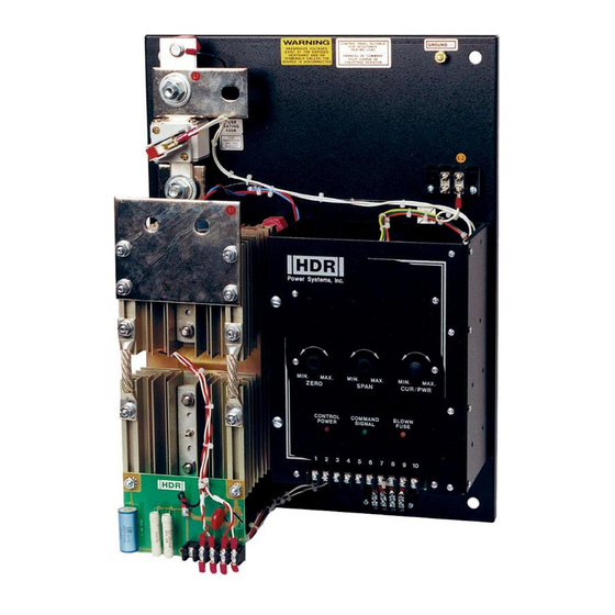
Page 18: Figure 4.1 Control Panel
The PF1 is calibrated at the Factory for the specified input type and normally does NOT need adjustment. However, should a setup be required use the following methods. Refer to chapter 3.5 for the Command signal input configuration. Ametek HDR Power Systems Rev 3... -
Page 19: Figure 4.2 Process Controller Input Connections
With the power to the PF1 turned off, connect the potentiometer as shown in Figure 4.3. The CW position is the full power output position. Terminal TB1-5 is internally connected to a positive dc voltage source. Rev 3 Ametek HDR Power Systems... -
Page 20: Figure 4.3 Remote Control With A Potentiometer
Figure 4.4 and remove jumper from terminal TB1-7 and TB1-8. Install the AUTO/MAN switch in the same general location as the remote manual potentiometer. Note that the full CW position of the potentiometer is the full-power-output position. Ametek HDR Power Systems Rev 3... -
Page 21: Figure 4.4 Auto/Man Control With Controller And Remote Potentiometer
Calibrate the system by performing the steps in 4.3. Note that zero power demand is accomplished by opening the contacts with the controller, and maximum power demand is present when the contacts are closed. Rev 3 Ametek HDR Power Systems... -
Page 22: Figure 4.6 Shutdown Control
When it is necessary to shutdown or disable the output, it is a simple matter. Connect a dry contact closure between terminals 3 and 4 of the firing circuit as shown in Figure 4.6. A closed contact will disable the PF1 output. Figure 4.6 Shutdown Control (Output Disabled By Contact Closure) Ametek HDR Power Systems Rev 3... -
Page 23: Figure 5.1 Current Limit/Trip Board
Adjust ZERO and SPAN as previously described. d. Adjust CURRENT LIMIT (CUR/PWR) potentiometer full CCW. e. Increase the input control signal to demand full output Adjust the CURRENT LIMIT (CUR/PWR) potentiometer until maximum current level is reached. Rev 3 Ametek HDR Power Systems... - Page 24 Adjust the CL potentiometer CCW until the maximum current starts to reduce. Option VIPR a. Set SW2 FB Closed. b. Adjust ZERO and SPAN as previously described in chapter 4. c. Set SW2 FB Open. Ametek HDR Power Systems Rev 3...
-
Page 25: Figure 5.2 Vipr Board
Potentiometer Voltage Current Power Resistance e. Set regulation for Voltage and SW6 to ON. Adjust P6 to the desired current limit level. The LED should light when in current limit. Figure 5.2 VIPR Board Rev 3 Ametek HDR Power Systems... - Page 26 Option Setup PF1 SCR Power Controller Ametek HDR Power Systems Rev 3...
-
Page 27: Figure 6.1 Ac Switch And Scr On-Time
For each cycle of input there is one cycle of oscillator output. By this Rev 3 Ametek HDR Power Systems... - Page 28 This protection is necessary to prevent large surge currents associated with transformers and similar loads when power is first applied to them. The circuit comes into play during startup or after a power interruption of several cycles’ duration. Ametek HDR Power Systems Rev 3...
- Page 29 Ametek HDR Power Systems emphasizes customer satisfaction by maintaining a rapid-response and cooperative customer-service. If operational difficulties occur, Ametek HDR Power Systems will provide replacement parts or units quickly, courteously and efficiently. If servicing problems arise that are not within the scope of the following troubleshooting guide, service is readily available, as detailed in Chapter 8.
- Page 30 If it is above 122 ºF (50 ºC), steps should be taken to provide more cooling, or the PF1 should be moved to a cooler location, or call the Ametek HDR Power Systems service department. Excessive Vibration. A significant degree of pitched or unpitched vibration can cause numerous problems.
-
Page 31: Table 7.1 Troubleshooting Chart (Symptoms And Solutions)
X1. On the Rx1 scale, the resistance should be infinite in both directions. If a shorted component is indicated in any of these cases, replace it. (2b) Firing control Return the power to the unit. If the problem persists, contact Ametek HDR section defective Power Systems service. - Page 32 Answering Service operator of the nature and degree of your problem. In such cases the operator is authorized to call Ametek HDR Power Systems Service. We cannot, however, guarantee that service assistance will be available at any given off-hour time.
-
Page 33: Table 8.1 Pf1 Spare Parts List
Fan, axial, 115 Vac, 100 CFM 4520001 Fuse, 630 A, 700 V 7500124 Lug Kit, 1 Phase 500 A 2710203 PCB Assy, PF1 Extended Gate 2099160 SCR, 800 A, 1400 V 5080114 PCB Assy, DVDT 2071000 Rev 3 Ametek HDR Power Systems... -
Page 34: Table 8.2 Pf1 Drawing List
Outline & Mounting, PF1 – 60 - 225 A M2710052 Outline & Mounting, PF1 – 350 A, 500 A M2710056 Outline & Mounting, PF1 – 650 A M2710058 Outline & Mounting, PF1 – 800, 1000, 1200 A M2710059 Ametek HDR Power Systems Rev 3... - Page 35 AMETEK HDR warrants that the equipment delivered will be free from defects in workmanship and material for a period of five years from the date of shipment. AMETEK HDR will repair or replace, at AMETEK HDR's option, any part found defective during proper and normal use, provided that written notice of the nature of the defect is received by AMETEK HDR within the five year warranty period and that the customer returns the part to AMETEK HDR freight paid both ways.
- Page 36 PF1 SCR Power Controller Field Service Repairs Repairs may be performed at your location. Please contact Ametek HDR Power Systems at (614) 308-5500 to discuss terms and conditions, to get the current service rates and to schedule field repairs at your location.
- Page 37 PF1 SCR Power Controller Appendix APPENDIX Appendix A – System Schematic Rev 3 Ametek HDR Power Systems...
- Page 38 Appendix PF1 SCR Power Controller Appendix B – 60-225 A Outline Ametek HDR Power Systems Rev 3...
- Page 39 PF1 SCR Power Controller Appendix Appendix C – 350-500 A Outline Rev 3 Ametek HDR Power Systems...
- Page 40 Appendix PF1 SCR Power Controller Appendix D – 650 A Outline Ametek HDR Power Systems Rev 3...
- Page 41 PF1 SCR Power Controller Appendix Appendix E – 800-1200 A Outline Rev 3 Ametek HDR Power Systems...
- Page 42 PF1 SCR Power Controller Appendix F – Declaration of Conformity EC DECLARATION OF CONFORMITY AMETEK HDR POWER SYSTEMS 503 Lakeview Plaza Blvd, Ste C Worthington, Ohio, 43085 - USA Declare under our sole responsibility that the products listed below and bearing the CE label:...
- Page 43 Notes:...
- Page 44 503 Lakeview Plaza Blvd, Ste C Worthington, Ohio, 43085 USA...
Need help?
Do you have a question about the PF1 SCR Series and is the answer not in the manual?
Questions and answers