Advertisement
Quick Links
Operator's
Manual
RIDER COOLING
SYSTEM
Model No. 132.24607
CAUTION:
Before using this product, read
this manual and follow all Safety
Rules and Operating Instructions.
IMPORTANT:
For replacement
parts
or
assembly
questions
call 800-320-MIST.
•
Safety
•
Assembly
•
Operation
•
Maintenance
•
Troubleshooting
Sears,
Roebuck
and Co., Hoffman
Estates,
IL 60179
U.S.A
www.oraftsman.com
Advertisement

Related Manuals for Craftsman 132.24607


Summary of Contents for Craftsman 132.24607
- Page 1 Operator's Manual RIDER COOLING Model No. 132.24607 CAUTION: Before using this product, read this manual and follow all Safety Rules and Operating Instructions. IMPORTANT: For replacement assembly questions call 800-320-MIST. Sears, Roebuck and Co., Hoffman www.oraftsman.com SYSTEM parts Estates, IL 60179 U.S.A...
-
Page 2: One Year Full Warranty
ONE YEAR FULL WARRANTY If this Craftsman product fails due to a defect in material or workmanship date of purchase, return it to any Sears store or other Craftsman outlet in the United States for free replacement. This warranty does not include the air or water fiIter, which are expendable from normal use within the warranty period. - Page 3 ... iii!iii iii_jiiiii ii_iiHiiiTi ¸ii - ¸? REF. QTY. DESCRIPTION Hex Bolt, 5/16"-18 x1-1/4" Flat Washer, 7/8" OD Cap Screw, 5t16-!8" Flat Washer, 5/8" OD Nylock Nut, 5/16"-18 Dash Adapter Nuts Routing Clips Rubber Washer Dash Adapter Spacer Cable Ties x 3/4"...
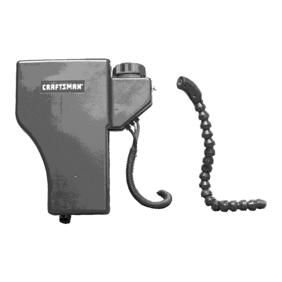
- Page 4 AA. P ower Unit BB. M isting Nozzle Assembly CC. M ounting Bracket DD. 9 /16" Drill Bit...
- Page 5 Tools Required ½" Socket Wrench w/Extension Allen Wrenches Power Drill Adjustable Wrench Mounting Power Unit To Tractor NOTE: If there is a 2 or 3 bin bagger installed on your tractor, you will need to remove the bagger from the tractor before proceeding. Leave the bagger bracket mounted to the vehi- cle.
- Page 6 Once a ll b olts h ave b een i nstalled, allnuts using allen wrench and socket onboth bolts and nuts, • Confirm the installation of all four screws (A) that hold the power unit (AA) to the mounting bracket (CC). tighten Mounting Misting...
- Page 7 Using supplied 9/16" drill b it ( DD), drill h ole through the dash a tthe bottom o fthe mounting location. Use caution n ot t o damage anything inthe engine com- partment while drilling hole. • Proceed to Step 2. Step lb (Tractors w/o mounting...
- Page 8 Step 3 IMPORTANT: Ifyou have n ot a lready done so, y ou must disconnect the negative (-)termi- nal ofthe battery before completing steps. NOTE: If a hole was drilled in a dash not equipped with mounting locations, you will need to slide the dash adapter spacer (I) over hoses of the misting arm assembly (BB) prior to proceeding.
- Page 9 Connecting Power Unit to Misting Arm Assembly Step 1 • Locate supply lines and power connector at the power unit (AA) and uncoil to full length. Starting at the rear of tractor, feed supply lines and connector assembly underneath tractor body along right side of chassis using care to avoid any potential interfer- ence with tractor functionality.
- Page 10 Step 3 • Locate BLACK supply tube from power unit and BLACK supply tube from misting nozzle assembly. • Remove protective caps from the BLACK supply tube and filter attached to the BLACK tube. • Connect BLACK supply tube from misting arm assembly to the filter installed on the BLACK supply tube from the power unit.
- Page 11 Step 3 • Connect power unit's female connector to Maintenance Minder. • Connect power unit male connector to tractor electrical connector just removed from Maintenance Minder in Step 10. Proceed to Finalizing System Installa- tion. Step 4 • From inside the engine compartment, locate tractor power supply connector.
- Page 12 Finalizing System Installation Step 1 • Review the illustration below to familiarize yourself with the suggested locations of the routing clips (G) EACH SIDE OF DASH FRAME IN WHEEL Install the three (3) routing clips (G) along the length of the supply tubes at the locations shown above.
- Page 13 Step 2 • Using a supplied cable tie (J) organize any excess length of supply tubes and stow behind battery (or along fuel tank if equipped). Secure supply tubes to electrical supply lines of tractor at convenient locations to prevent line damage during tractor operation.
- Page 14 KNOW YOUR RIDER COOLING SYSTEM Read this owner's manual before operating. Compare the illustration below with your rider cooling system to familiarize yourself with the various features and their locations. BEFORE STARTING • Use end of assembly checklist to verify that alI instructions have been properly completed.
- Page 15 HOW TO START YOUR COOLING SYSTEM • With the tractor key in "ON" position, toggle power switch on unit to "ON" posi- tion. NOTE: It is normal to experience the time the system is turned on to the deliv- ery of mist from the nozzle. If this exceeds 2 minutes, refer to the troubleshooting HOW TO STOP YOUR RIDER COOLING SYSTEM...
- Page 16 CUSTOMER RESPONSIBILITIES Read and follow the maintenance section. VIA1NTENANCE SCHEDULE sill in dates as you complete "egular service Sh eck for loose fasten ers Slean Exterior Zmpty Water Tank Clean Basket Filter Sor_dition Water Tank :_eplace Ah-fWater Filters EMPTYING WATER TANK •...
- Page 17 • Empty water tank completely, cap, and run system to evacuate all wa- ter in supply lines. • Store misting nozzle assembly by folding over dash of tractor. • Ensure the power switch on the power unit is in the "OFF" position. PROBLEM CAUSE Pump Not...
- Page 18 NOTES:...
- Page 19 NOTES:...
- Page 20 For expert troubleshooting manage www,managemyhome,com For repair- in your home - of all major brand appliances, lawn and garden equipment, or heating and cooling systems, no matter who made it, no matter who sold it! For the replacement parts, accessories and owner's manuals that you need to dodt_yourself, For Sears professional installation of home appiiances and items like garage door openers and water heaters,...
Need help?
Do you have a question about the 132.24607 and is the answer not in the manual?
Questions and answers