Table of Contents
Advertisement
Quick Links
Advertisement
Table of Contents
Troubleshooting

Subscribe to Our Youtube Channel
Related Manuals for Brooks Instrument 585 EMH Series


Summary of Contents for Brooks Instrument 585 EMH Series
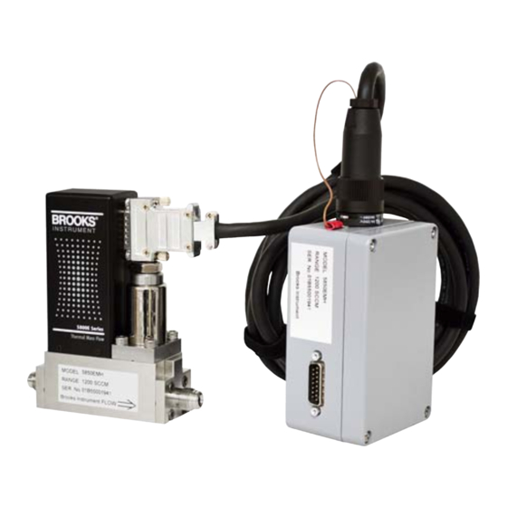
- Page 1 Installation and Operation Manual X-TMF-585xEMH-MFC-eng Part Number: 541B212AAG ® Brooks Model 585xEMH May, 2017 ® Brooks Model 585xEMH High Temperature Mass Flow Controllers Model 5850EMH High Temperature Model 5851EMH High Temperature Thermal Mass Flow Controller Thermal Mass Flow Controller...
- Page 2 Read before proceeding! Brooks Instrument designs, manufactures and tests its products to meet many national and international standards. These products must be properly installed, operated and maintained to ensure they continue to operate within their normal specifications. The following instructions must be adhered to and integrated into your safety program when installing, operating and maintaining Brooks Instrument products.
- Page 3 We appreciate this opportunity to service your flow measurement and control requirements with a Brooks Instrument device. Every day, flow customers all over the world turn to Brooks Instrument for solutions to their gas and liquid low-flow applications. Brooks provides an array of flow measurement and control products for various industries from biopharmaceuticals, oil and gas, fuel cell research and chemicals, to medical devices, analytical instrumentation, semiconductor manufacturing, and more.
- Page 4 Installation and Operation Manual X-TMF-585xEMH-MFC-eng Part Number: 541B212AAG ® Brooks Model 585xEMH May, 2017 THIS PAGE WAS INTENTIONALLY LEFT BLANK...
-
Page 5: Table Of Contents
Contents Installation and Operation Manual X-TMF-585xEMH-MFC-eng Part Number: 541B212AAG Brooks ® Model 585xEMH May, 2017 Paragraph Page Number Number Section 1 Introduction How to Use This Manual ......................1-1 Description ..........................1-1 Specifications ..........................1-1 Section 2 Installation General ............................2-1 Receipt of Equipment ......................... - Page 6 Contents Installation and Operation Manual X-TMF-585xEMH-MFC-eng Part Number: 541B212AAG Brooks ® Model 585xEMH May, 2017 Figures Figure Page Number Number Dimensions - Model 585xEMH with D-Connector and VCR Fittings .......... 1-3 MFC Mounting Hole Positions for Models 5850EMH & 5851EMH ..........2-3 Connecting and Tightening Process Connections ..............
-
Page 7: Section 1 Introduction
Section 1 Introduction Installation and Operation Manual X-TMF-585xEMH-MFC-eng Part Number: 541B212AAG ® Brooks Model 585xEMH May, 2017 1-1 How to Use This Manual This instruction manual is intended to provide the user with all the ® information necessary to install, operate and maintain the Brooks Models 5850EMH and 5851EMH. - Page 8 Section 1 Introduction Installation and Operation Manual X-TMF-585xEMH-MFC-eng Part Number: 541B212AAG ® Brooks Model 585xEMH May, 2017 Table 1-1 585xEMH Specifications P P P P P erformance erformance erformance erformance erformance 5850EMH 5850EMH 5850EMH 5850EMH 5850EMH 5851EMH 5851EMH 5851EMH 5851EMH 5851EMH Flow Range Flow Range...
-
Page 9: Dimensions - Model 585Xemh With D-Connector And Vcr Fittings
Section 1 Introduction Installation and Operation Manual X-TMF-585xEMH-MFC-eng Part Number: 541B212AAG ® Brooks Model 585xEMH May, 2017 5850EMH 5851EMH Figure 1-1 Dimensions - Model 585xEMH with D-Connector and VCR Fittings... - Page 10 Section 1 Introduction Installation and Operation Manual X-TMF-585xEMH-MFC-eng Part Number: 541B212AAG ® Brooks Model 585xEMH May, 2017 THIS PAGE WAS INTENTIONALLY LEFT BLANK...
-
Page 11: Section 2 Installation
If the packing case is damaged, the local carrier should be notified at once regarding his liability. A report should be submitted to the nearest Brooks Instrument location listed on the Global Service Network page on our website: BrooksInstrument.com/GlobalSupportCenters... -
Page 12: Transit Precautions
Section 2 Installation Installation and Operation Manual X-TMF-585xEMH-MFC-eng Part Number: 541B212AAG ® Brooks Model 585xEMH May, 2017 2-5 Transit Precautions To safeguard the instrument against transportation damage, it is recommended to keep the instrument in its factory container until ready for installation. -
Page 13: Mfc Mounting Hole Positions For Models 5850Emh & 5851Emh
Section 2 Installation Installation and Operation Manual X-TMF-585xEMH-MFC-eng Part Number: 541B212AAG ® Brooks Model 585xEMH May, 2017 d. The Model 585xEM Mass Flow Controller can be installed in any position. However, mounting in orientations other than the original factory calibration (see calibration data sheet) can result in a full scale shift after re-zeroing. -
Page 14: Connecting And Tightening Process Connections
Section 2 Installation Installation and Operation Manual X-TMF-585xEMH-MFC-eng Part Number: 541B212AAG ® Brooks Model 585xEMH May, 2017 g. Once the controller is correctly mounted, connect the inlet and outlet ® fittings to the gas supply line. 1. Install new gaskets compatible with the gas to be used. 2. -
Page 15: Electrical Interface
Section 2 Installation Installation and Operation Manual X-TMF-585xEMH-MFC-eng Part Number: 541B212AAG ® Brooks Model 585xEMH May, 2017 Figure 2-3 Remote Electronics Box Mounting Diagram The remote electronics box can be mounted in any position that is convenient, within reach of the high temperature cable. The temperature limit of the electronics is 0-50°C (32°F-122°F). -
Page 16: Operation Procedure
Section 2 Installation Installation and Operation Manual X-TMF-585xEMH-MFC-eng Part Number: 541B212AAG ® Brooks Model 585xEMH May, 2017 Figure 2-4 Common Electrical Hookups 2-9 Operation Procedure a. Mount the controller & remote electronics box in their final location and orientation. b. Apply any and all heater devices and thermal insulation around the controller and the process lines. -
Page 17: Section 3 Operation
Section 3 Operation Installation and Operation Manual X-TMF-585xEMH-MFC-eng Part Number: 541B212AAG ® Brooks Model 585xEMH May, 2017 3-1 Overview After the flowmeter has been properly installed in the process line, it is ready for operation. When initiating flow, slowly open the valve to avoid a flow surge. -
Page 18: Externally Accessible Adjustments At Remote Electronics Box
Section 3 Operation Installation and Operation Manual X-TMF-585xEMH-MFC-eng Part Number: 541B212AAG ® Brooks Model 585xEMH May, 2017 Figure 3-2 Externally Accessible Adjustments at Remote Electronics Box Figure 3-3 External 15-Pin D-Sub Connector at Remote Electronics 15 Pin D-Connector 15 Pin D-Connector 15 Pin D-Connector 15 Pin D-Connector 15 Pin D-Connector... -
Page 19: Flow Sensor Operational Diagram
Section 3 Operation Installation and Operation Manual X-TMF-585xEMH-MFC-eng Part Number: 541B212AAG ® Brooks Model 585xEMH May, 2017 3-3 Theory of Operation The thermal mass flow sensing technique used in the Model 585xEMH operates as follows: A precision power supply provides a constant power heat input (P) at the heater which is located at the midpoint of the sensor tube. -
Page 20: Flow Control System Block Diagram
Section 3 Operation Installation and Operation Manual X-TMF-585xEMH-MFC-eng Part Number: 541B212AAG ® Brooks Model 585xEMH May, 2017 Figure 3-6 Flow Control System Block Diagram Figure 3-7 Customer Connections and Settings... -
Page 21: Features
Section 3 Operation Installation and Operation Manual X-TMF-585xEMH-MFC-eng Part Number: 541B212AAG ® Brooks Model 585xEMH May, 2017 The flow restrictor shown in Figure 3-5 performs a ranging function similar to a shunt resistor in an electrical ammeter. The restrictor provides a pressure drop that is linear with flow rate. -
Page 22: Adjustment Potentiometers
Section 3 Operation Installation and Operation Manual X-TMF-585xEMH-MFC-eng Part Number: 541B212AAG ® Brooks Model 585xEMH May, 2017 3-5 Adjustment Potentiometers All Model 585xEMH instruments are factory calibrated for optimum performance. The only potentiometer recommended for field adjustment is the Zero. Reference Figure 3-2 to access the Zero Potentiometer adjustment screw. -
Page 23: Zero Adjustment
Calibration of the Model 585xEMH mass flow controller requires the use of a digital voltmeter (DVM) and a precision flow standard calibrator such as the Brooks Instrument’s Vol-U-Meter. It is recommended that the calibration be performed only by trained and qualified service personnel. -
Page 24: Bench Troubleshooting Circuit
Section 3 Operation Installation and Operation Manual X-TMF-585xEMH-MFC-eng Part Number: 541B212AAG ® Brooks Model 585xEMH May, 2017 Figure 3-8 Bench Troubleshooting Circuit Calibration Procedure for the Standard Response PC Board a. With the controller installed in an unpressurized gas line, apply power and allow approximately 45 minutes for warm-up. - Page 25 Section 3 Operation Installation and Operation Manual X-TMF-585xEMH-MFC-eng Part Number: 541B212AAG ® Brooks Model 585xEMH May, 2017 Note: The voltage at TP1 is -100 times the output voltage of the sensor. This voltage can range from -1.2 to -12 Volts, however, it is recommended that this voltage stay between -2.0 and -9.0 Volts for proper operation.
-
Page 26: Response Adjustment
Section 3 Operation Installation and Operation Manual X-TMF-585xEMH-MFC-eng Part Number: 541B212AAG ® Brooks Model 585xEMH May, 2017 Note: The voltage at TP2 can range from -10 to +3 Volts. It is recommended, however, that this voltage stay between -2.5 and +2.5 Volts for proper operation. -
Page 27: Response Adjustment
Section 3 Operation Installation and Operation Manual X-TMF-585xEMH-MFC-eng Part Number: 541B212AAG ® Brooks Model 585xEMH May, 2017 a. Set the command to zero percent flow rate (0.000 V) and allow the flow signal output to stabilize (30 seconds minimum). Step change the command to 100% of flow (5.000 V) and record the output signal from the fast response flowmeter. - Page 28 Section 3 Operation Installation and Operation Manual X-TMF-585xEMH-MFC-eng Part Number: 541B212AAG ® Brooks Model 585xEMH May, 2017 THIS PAGE WAS INTENTIONALLY LEFT BLANK 3-12...
-
Page 29: Overview
Section 4 Maintenance & Installation and Operation Manual X-TMF-585xEMH-MFC-eng Troubleshooting Part Number: 541B212AAG Brooks ® Model 585xEMH May, 2017 4-1 Overview... -
Page 30: Troubleshooting
The breakout board( P/N S273Z668AAA) D-Connector version available from Brooks Instrument, will make this job much easier. 2. Verify that the process gas connections have been correctly terminated and leak-checked. - Page 31 Note: Do not attempt to disassemble the sensor. D. Cleaning Procedures No routine external cleaning is required for Brooks thermal mass flow controller. Should the 585xEMH Mass Flow Controller require cleaning due to deposition, return the device to Brooks Instrument for servicing by trained technicians.
- Page 32 Section 4 Maintenance & Installation and Operation Manual X-TMF-585xEMH-MFC-eng Troubleshooting Part Number: 541B212AAG Brooks ® Model 585xEMH May, 2017 Table 4-1 Bench Troubleshooting Trouble Possible Cause Check/Corrective Action Actual flow overshoots setpoint by Anticipate potentiometer out of adjustment. Adjust anticipate potentiometer. Refer to Sections 3-5 & 3-8 . more than 5% full scale.
- Page 33 Section 4 Maintenance & Installation and Operation Manual X-TMF-585xEMH-MFC-eng Troubleshooting Part Number: 541B212AAG Brooks ® Model 585xEMH May, 2017 Table 4-2 Sensor Troubleshooting SENSOR SCHEMATIC FUNCTION Heater Upstream Temperature Sensor (Su) Downstream Temperature Sensor (Sd) Sensor Common Heater Common Remove the sensor connector from the PC Board for this procedure. OHMMETER CONNECTION RESULT IF ELECTRICALLY FUNCTIONAL Open circuit on ohmmeter.
- Page 34 Section 4 Maintenance & Installation and Operation Manual X-TMF-585xEMH-MFC-eng Troubleshooting Part Number: 541B212AAG Brooks ® Model 585xEMH May, 2017 In order to calculate the conversion factor for a gas mixture, the following formula should be used: Where, = percentage (%) of gas 1 (by volume) = percentage (%) of gas 2 (by volume) = percentage (%) of gas n (by volume) Example: The desired gas is 20% Helium (He) and 80% Chlorine (Cl) by...
- Page 35 Section 4 Maintenance & Installation and Operation Manual X-TMF-585xEMH-MFC-eng Troubleshooting Part Number: 541B212AAG Brooks ® Model 585xEMH May, 2017 Table 4-3 Conversion Factors (Nitrogen Base) DENSITY SENSOR ORIFICE GAS NAME FORMULA SEMI ID FACTOR FACTOR (km/m 1 1 2-Trichloro-1 1 2-Triflouroet f-113 C2Cl3F3 0.231 2.520...
- Page 36 Section 4 Maintenance & Installation and Operation Manual X-TMF-585xEMH-MFC-eng Troubleshooting Part Number: 541B212AAG Brooks ® Model 585xEMH May, 2017 Table 4-3 Conversion Factors (Nitrogen Base) (Continued) DENSITY SENSOR ORIFICE GAS NAME FORMULA SEMI ID FACTOR FACTOR (km/m Bromine Pentafluoride BrF5 0.287 2.502 7.806...
- Page 37 Section 4 Maintenance & Installation and Operation Manual X-TMF-585xEMH-MFC-eng Troubleshooting Part Number: 541B212AAG Brooks ® Model 585xEMH May, 2017 Table 4-3 Conversion Factors (Nitrogen Base) (Continued) DENSITY SENSOR ORIFICE GAS NAME FORMULA SEMI ID FACTOR FACTOR (km/m Diethylsilane C4H12Si 0.183 1.775 3.940 Difluoromethane...
- Page 38 Section 4 Maintenance & Installation and Operation Manual X-TMF-585xEMH-MFC-eng Troubleshooting Part Number: 541B212AAG Brooks ® Model 585xEMH May, 2017 Table 4-3 Conversion Factors (Nitrogen Base) (Continued) DENSITY SENSOR ORIFICE GAS NAME FORMULA SEMI ID FACTOR FACTOR (km/m Hydrogen Iodide 0.953 2.144 5.789 Hydrogen Selenide...
- Page 39 Section 4 Maintenance & Installation and Operation Manual X-TMF-585xEMH-MFC-eng Troubleshooting Part Number: 541B212AAG Brooks ® Model 585xEMH May, 2017 Table 4-3 Conversion Factors (Nitrogen Base) (Continued) DENSITY SENSOR ORIFICE GAS NAME FORMULA SEMI ID FACTOR FACTOR (km/m Oxygen 0.988 1.067 1.429 Oxygen Difluoride 0.672...
- Page 40 Section 4 Maintenance & Installation and Operation Manual X-TMF-585xEMH-MFC-eng Troubleshooting Part Number: 541B212AAG Brooks ® Model 585xEMH May, 2017 Table 4-3 Conversion Factors (Nitrogen Base) (Continued) DENSITY SENSOR ORIFICE GAS NAME FORMULA SEMI ID FACTOR FACTOR (km/m Trichlorofluoromethane f-11 CCl3F 0.374 2.244 6.281...
-
Page 41: Orifice Sizing
Section 4 Maintenance & Installation and Operation Manual X-TMF-585xEMH-MFC-eng Troubleshooting Part Number: 541B212AAG Brooks ® Model 585xEMH May, 2017 4-4 Orifice Sizing The Orifice Sizing Nomograph, Figure 4-1, is used to calculate the control valve's orifice size when changing any or all of the following factors from the original factory calibration: operating pressure (inlet and outlet) flow range... - Page 42 Section 4 Maintenance & Installation and Operation Manual X-TMF-585xEMH-MFC-eng Troubleshooting Part Number: 541B212AAG Brooks ® Model 585xEMH May, 2017 Figure 4-1 Model 585xEMH Orifice Sizing Nomograph 4-14...
- Page 43 Section 4 Maintenance & Installation and Operation Manual X-TMF-585xEMH-MFC-eng Troubleshooting Part Number: 541B212AAG Brooks ® Model 585xEMH May, 2017 Example: 2,000 sccm 2,000 x .269 538 sccm Nitrogen In order to calculate the orifice conversion factor when using a gas mixture, the following formula must be used: Where percentage by volume of gas 1...
- Page 44 Section 4 Maintenance & Installation and Operation Manual X-TMF-585xEMH-MFC-eng Troubleshooting Part Number: 541B212AAG Brooks ® Model 585xEMH May, 2017 3. Determine Critical Pressure Drop Critical pressure drop occurs when the outlet pressure (psia) is less than half the inlet pressure (psia) or If these conditions exist, the pressure drop (Dp) should be calculated as follows: Dp =...
-
Page 45: Restrictor Sizing
Section 4 Maintenance & Installation and Operation Manual X-TMF-585xEMH-MFC-eng Troubleshooting Part Number: 541B212AAG Brooks ® Model 585xEMH May, 2017 Figure 4-2 Example Nomograph 4-5 Restrictor Sizing The restrictor assembly is a ranging device for the sensor portion of the controller. It creates a pressure drop which is linear with flow rate. This diverts a sample quantity of the process gas flow through the sensor. - Page 46 Sizing All Model 585xEMH Series Restrictor Assemblies are factory adjusted to provide a specific pressure drop for each flow rate. This corresponds to the desired full scale flow rate. Contacts Brooks Instrument for recommended restrictor size and part number. Example: The desired gas is Silane (SiH4).
-
Page 47: Section A Essential Instructions
Section A Essential Instructions Installation and Operation Manual X-TMF-585xEMH-MFC-eng Part Number: 541B212AAG May, 2017 ® Brooks Model 585xEMH Bulgarian Brooks Instrument Brooks Instrument. Brooks Instrument : (1) . (2) Brooks Instrument (PED) 0,5 bar (g) 25 mm 1" (inch), (PED). - Page 48 P ed instalací si p e t te následující instrukce! Spole nost Brooks Instrument konstruuje, vyrábí a testuje tento produkt tak, aby splnil mnoho národních a mezinárodních standard . P ístroje musí být ádn nainstalovány, používány a udržovány tak, aby byl zajišt n jejich nep etržitý provoz v rámci normálních technických specifikací. Musíte dodržovat následující...
- Page 49 Section A Essential Instructions Installation and Operation Manual X-TMF-585xEMH-MFC-eng Part Number: 541B212AAG May, 2017 ® Brooks Model 585xEMH Dansk Grundlæggende vejledninger Læs disse før anvendelse! Brooks Instruments designer, fremstiller og afprøver sine produkter således, at de tilpasser sig både de indenrigs og internationale standarder. Disse udstyr bør installeres, bruges og repareres omhyggeligt, så...
- Page 50 Lees ze voordat u verder gaat! Brooks Instrument ontwerpt, produceert en test haar producten zodanig dat ze voldoen aan vele nationale en internationale normen. Deze producten moeten correct worden geïnstalleerd, bediend en onderhouden zodat ze binnen hun normale specificaties blijven werken.
- Page 51 Olulised juhised Enne kasutamist lugege hoolikalt läbi! Brooks Instrument konstrueerib, valmistab ja katsetab oma tooteid selliselt, et need vastaksid paljudele riiklikele ja rahvusvahelistele standarditele. Ainult nõuetekohane paigaldamine, kasutamine ja hooldamine tagab toodete katkematu talitluse tavaspetsifikatsiooni raames. Brooks Instrumenti toodete paigaldamisel, kasutamisel ja hooldamisel tuleb täita alljärgnevaid juhiseid ja integreerida need asjakohasesse ohutusprogrammi.
- Page 52 Perusohjeet Lue ensin ohjeet huolellisesti! Brooks Instrument suunnittelee, valmistaa ja testaa laitteensa vastaamaan useimpien kotimaisten ja kansainvälisten standardien vaatimuksia. Tuotteet tulee asentaa, käyttää ja huoltaa käyttöohjeiden mukaan jotta niiden toimivuus taataan. Brooks Instrumentin laitteiden asennuksessa, käytössä ja huollossa on noudatettava soveltuvia määräyksiä ja ohjeita, lisäksi mainitut ohjeet on huomioitava työsuojelun ohjeistuksessa.
- Page 53 AVERTISSEMENT: n’utilisez pas cet instrument au-delà des spécifications énumérées dans le manuel d’utilisation. Le non-respect de cet avertissement peut entraîner de graves blessures et / ou endommager l’équipement. • Si vous ne comprenez pas l’une des instructions, prenez contact avec un représentant de Brooks Instrument pour obtenir des explications. •...
- Page 54 Produkte mit einer Größe von 25 mm oder 1“ (inch) oder kleiner sind Sound Engineering Practice (SEP). Europäische Verordnung zur elektromagnetischen Verträglichkeit (EMV) Geräte von Brooks Instrument (elektrischer und elektronischer Art) mit CE-Zeichen haben den Test auf Einhaltung der Verordnung zur elektromagnetischen Verträglichkeit (EMV Richtlinie 2014/30/EU) erfolgreich bestanden.
- Page 55 Section A Essential Instructions Installation and Operation Manual X-TMF-585xEMH-MFC-eng Part Number: 541B212AAG May, 2017 ® Brooks Model 585xEMH Greek Brooks Instrument Brooks Instrument. ’ Brooks Instrument. : (1) . (2) Brooks Instrument. (PED) 0,5 bar (g) 25 mm (PED). PED.
- Page 56 üzemeltetni és karbantartani ahhoz, hogy mindenképpen a normál m ködési tartományuknak megfelel en üzemelhessenek. Az alábbi utasításokat be kell tartani, és be kell építeni a munkavédelmi programba a Brooks Instrument termékeinek telepítése, üzemeltetése és karbantartása során.
- Page 57 Direttiva europea relativa alla compatibilità elettromagnetica (EMC) Le apparecchiature (elettriche/elettroniche) Brooks Instrument dispongono del marchio CE ed hanno superato positivamente i test per i requisiti di compatibilità elettromagnetica (Direttiva EMC 2014/30/EU). In ogni caso bisogna prestare particolare attenzione alla scelta dei cavi di segnale utilizzati per le apparecchiature con marchio CE.
- Page 58 Lai nodrošin tu šo izstr d jumu turpm ku darb bu atbilstoši noteiktajiem parametriem, tie ir pareizi j uzst da, j lieto un j apkopj. Uzst dot, lietojot „Brooks Instrument” izstr d jumus un veicot to apkopi, ir j iev ro šie nor d jumi un j iek auj tie j su droš bas programm .
- Page 59 SP JIMAS: nenaudokite šio prietaiso viršydami instrukcijoje ir eksploatacijos vadove nurodytus techninius duomenis. Nesilaikydami šio sp jimo galite sunkiai susižeisti ir (arba) sugadinti rang . Jei nesuprantate koki nors nurodym , kreipkit s „Brooks Instrument“ atstov , kad paaiškint . Paisykite vis sp jim , persp jim ir nurodym , pažym t ant gaminio arba pateikt su juo.
- Page 60 Produkty o wielko ci 25 mm lub 1 cala lub mniejsze podlegaj zaleceniom „Uznanej Praktyki In ynierskiej” (SEP). Europejska dyrektywa dotycz ca kompatybilno ci elektromagnetycznej (EMC) Urz dzenia elektryczne / elektroniczne firmy Brooks Instrument posiadaj ce oznaczenie CE, przesz y pozytywnie testy pod k tem spe niania przez nich wymogów kompatybilno ci elektromagnetycznej (Dyrektywa EMC 2014/30/EU).
- Page 61 Ler antes de proceder! A Brooks Instrument projecta, fabrica e testa os seus produtos de forma a satisfazer numerosas normas nacionais e internacionais. Estes equipamentos devem ser instalados, utilizados e mantidos de forma adequada, e devem funcionar dentro da sua gama de utilização. As instruções seguintes devem ser, durante a instalação, uso e/ou manutenção dos equipamentos da Brooks Instrument, apreendidas e integradas no plano de...
- Page 62 În m sura în care indica iile c r ii ma inii nu sunt suficient de l muritoare, lua i leg tura cu reprezentantul Brooks Instrument pentru clarificarea problemei.
- Page 63 Pre íta pred inštaláciou! Brooks Instrument svoje výrobky projektuje, vyrába a testuje takým spôsobom, aby tieto vyhoveli domácim aj medzinárodným normám. Tieto zariadenia je potrebné predpísaným spôsobom inštalova , prevádzkova a udržiava , na zabezpe enie ich spo ahlivej a normálnej prevádzky v celom pracovnom rozsahu.
- Page 64 Pred servisom morate odstraniti tlak v obdelovalni liniji. e potrebujete rezervne dele, zagotovite, da usposobljeno osebje uporablja rezervne dele, ki jih je odobrila družba Brooks Instrument. Neodobreni deli in postopki lahko vplivajo na u inkovitost delovanja izdelka ali ogrozijo varno upravljanje postopka.
- Page 65 ¡Léalos primero! El Brooks Instrument proyecta, fabrica y prueba sus productos de manera que éstos respondan a numerosas normas nacionales e internacionales. Dichas instalaciones deben ser emplazadas, operadas y mantenidas adecuadamente, para que puedan marchar de todas formas en conformidad con el alcance normal de funcionamiento.
- Page 66 Läs detta innan du fortsätter! Brooks Instrument konstruerar, tillverkar och testar sina produkter med syfte att uppfylla alla nationella och internationella standarder. Dessa produkter måste installeras på rätt sätt, handhas och underhållas för att de skall fungera kontinuerligt enligt deras normala specifikation. De följande anvisningarna bör följas och integreras till Ert säkerhetsprogram varje gång när Brooks Instruments produkter installeras, handhas och underhålls.
- Page 67 Installation and Operation Manual X-TMF-585xEMH-MFC-eng Part Number: 541B212AAG ® Brooks Model 585xEMH May, 2017 THIS PAGE WAS INTENTIONALLY LEFT BLANK...
- Page 68 Brooks Instrument can provide customer seminars and dedicated training to engineers, end users and maintenance persons. Please contact your nearest sales representative for more details. Due to Brooks Instrument's commitment to continuous improvement of our products, all specifications are subject to change without notice. TRADEMARKS Brooks is a trademark of Brooks Instrument, LLC All other trademarks are the property of their respective owners.
Need help?
Do you have a question about the 585 EMH Series and is the answer not in the manual?
Questions and answers