Table of Contents
Advertisement
Installation and Operation Manual
X -TMF-5964-5850EM-MFC-eng
Part Number: 541B121AHG
November, 2008
®
Brooks
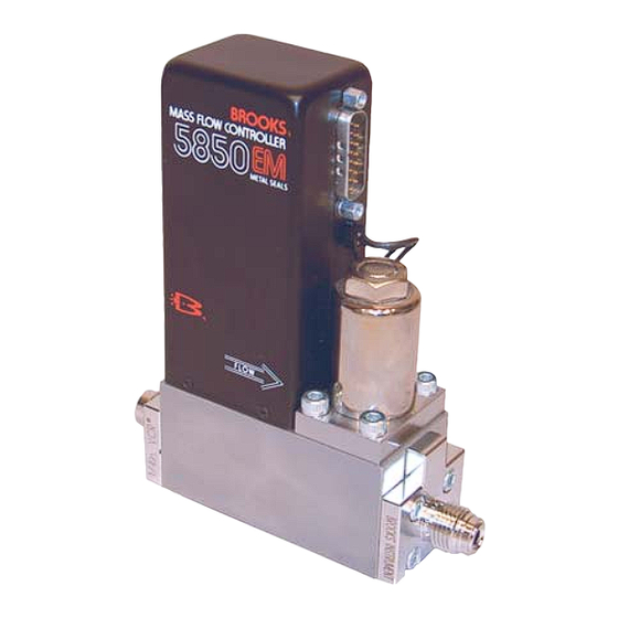
Models 5964, 5850EM
Mass Flow Controllers
Model 5964
Mass Flow Controller
with D-Connector
Brooks
Model 5850EM
Mass Flow Controller
with D-Connector
®
Models 5964, 5850EM
Model 5850EM Downported
Mass Flow Controller
with Card Edge
Advertisement
Table of Contents
Troubleshooting

Subscribe to Our Youtube Channel
Related Manuals for Brooks Instrument 5850EM


Summary of Contents for Brooks Instrument 5850EM
- Page 1 Installation and Operation Manual X -TMF-5964-5850EM-MFC-eng Part Number: 541B121AHG ® Brooks Models 5964, 5850EM November, 2008 ® Brooks Models 5964, 5850EM Mass Flow Controllers Model 5964 Mass Flow Controller with D-Connector Model 5850EM Downported Mass Flow Controller with Card Edge...
- Page 2 Essential Instructions Read this page before proceeding! Brooks Instrument designs, manufactures and tests its products to meet many national and international standards. Because these instruments are sophisticated technical products, you must properly install, use and maintain them to ensure they continue to operate within their normal specifications.
- Page 3 We appreciate this opportunity to service your flow measurement and control requirements with a Brooks Instrument device. Every day, flow customers all over the world turn to Brooks Instrument for solutions to their gas and liquid low-flow applications. Brooks provides an array of flow measurement and control products for various industries from biopharmaceuticals, oil and gas, fuel cell research and chemicals, to medical devices, analytical instrumentation, semiconductor manufacturing, and more.
- Page 4 Installation and Operation Manual X -TMF-5964-5850EM-MFC-eng Part Number:541B121AHG Brooks ® Models 5964, 5850EM November, 2008 THIS PAGE WAS INTENTIONALLY LEFT BLANK...
-
Page 5: Table Of Contents
Installation and Operation Manual Contents X -TMF-5964-5850EM-MFC-eng Part Number: 541B121AHG Brooks ® Models 5964, 5850EM November, 2008 Paragraph Page Number Number Section 1 Introduction How to Use This Manual ......................1-1 Description ..........................1-1 Specifications ..........................1-2 Section 2 Installation General ............................ - Page 6 Card Edge and VCR Fittings .................... 1-6 MFC/MFM Dimensional Drawing for Model 5964/5850EM Downported with D-Connector ..1-7 MFC/MFM Dimensional Drawing for Model 5964/5850EM Downported with Card Edge ..1-8 Card Edge Connector ......................2-6 20 Pin Card Edge Connector Ribbon Cable Hookup Diagram ..........2-7 D-Connector Shielded Cable Hookup Diagram - Voltage I/O Version ........
-
Page 7: Section 1 Introduction
Warranty, Local Sales/Service Contact Information 1-2 Description The Brooks Models 5964 and 5850EM Mass Flow Controllers is used in gas flow handling systems where very low leakage and high performance are required. The Models 5964 and 5850EM incorporates metal seals or welded joints, insuring leak integrity for high purity and high vacuum applications. -
Page 8: Specifications
Full Scale of final value for a 0-100% command step with Normally Closed Valve. (Optional on 5850EM). Model 5850EM: Less than 3 seconds to within 2% of Full Scale of final value for a 0-100% command step with Normally Closed Valve.* *Per SEMI Guideline E17-91. - Page 9 Installation and Operation Manual Section 1 Introduction X-TMF-5964-5850EM-MFC-eng Part Number: 541B121AHG ® Brooks Models 5964, 5850EM November, 2008 Differential Pressure Valve orifice sized for any pressure drop between 5 to 50 psi (Minimum pressure drop depends on gas and range). Ambient Temperature Limits Operating: 40°F to 150°F (5°C to 65°C)
- Page 10 Installation and Operation Manual Section 1 Introduction X-TMF-5964-5850EM-MFC-eng Part Number: 541B121AHG ® Brooks Models 5964, 5850EM November, 2008 ELECTRICAL CHARACTERISTICS (continued): 5 Volt Reference Output 5 Volts, ±0.01 Vdc into 2,000 ohms minimum Power Requirements Voltage Option: N.C. Valve (or N.O. Valve with flow less than 2.5 slpm): 3.25 watts max., + 15 Vdc @ 35 mA -15 Vdc @ 180 mA...
-
Page 11: Mfc/Mfm Dimensional Drawing For Model 5964/5850Em With D-Connector And Vcr Fittings
Installation and Operation Manual Section 1 Introduction X-TMF-5964-5850EM-MFC-eng Part Number: 541B121AHG ® Brooks Models 5964, 5850EM November, 2008 Figure 1-1 MFC/MFM Dimensional Drawing for Model 5964/5850EM with D-Connector and VCR Fittings... -
Page 12: Mfc/Mfm Dimensional Drawing For Model 5964/5850Em With Card Edge And Vcr Fittings
Installation and Operation Manual Section 1 Introduction X-TMF-5964-5850EM-MFC-eng Part Number: 541B121AHG ® Brooks Models 5964, 5850EM November, 2008 Figure 1-2 MFC/MFM Dimensional Drawing for Model 5964/5850EM with Card Edge and VCR Fittings... -
Page 13: Mfc/Mfm Dimensional Drawing For Model 5964/5850Em Downported With D-Connector
Installation and Operation Manual Section 1 Introduction X-TMF-5964-5850EM-MFC-eng Part Number: 541B121AHG ® Brooks Models 5964, 5850EM November, 2008 Figure 1-3 MFC/MFM Dimensional Drawing for Model 5964/5850EM Downported with D-Connector... -
Page 14: Mfc/Mfm Dimensional Drawing For Model 5964/5850Em Downported With Card Edge
Installation and Operation Manual Section 1 Introduction X-TMF-5964-5850EM-MFC-eng Part Number: 541B121AHG ® Brooks Models 5964, 5850EM November, 2008 Figure 1-4 MFC/MFM Dimensional Drawing for Model 5964/5850EM Downported with Card Edge... -
Page 15: Section 2 Installation
Section 2 Installation X-TMF-5964-5850EM-MFC-eng Part Number: 541B121AHG ® Brooks Models 5964, 5850EM November, 2008 2-1 General This section contains the procedures for the receipt and installation of the instrument. See Section 1 for dimensional and connection requirements. Do not attempt to start the system until the instrument has been permanently installed. -
Page 16: Return Shipment
Instrument must have been purged in accordance with the following: All flow instruments returned to Brooks requires completion of Form RPR003-1, Brooks Instrument Decontamination Statement, along with a Material Safety Data Sheet (MSDS) for the fluid(s) used in the instrument. -
Page 17: In-Line Filter
Recommended installation procedures: a. The Model 5964/5850EM should be located in a clean, dry atmo- sphere relatively free from shock and vibration. b. Leave sufficient room for access to the electrical components, span and zero potentiometers. -
Page 18: Electrical Interface
Final torque values depend on the screw and hardware material and lubrication. e. The control valve in the Model 5964/5850EM provides precision control and is not designed for positive shut-off. If positive shut-off is required, it is recommended that a separate shut-off valve be installed in-line. -
Page 19: Operation Procedure
Appendix A for CE Certification of Mass Flow Equipment. Note: If older Brooks secondary electronics are used to power and control the Model 5964/5850EM, the 5 Volt reference must be enabled. Brooks secondary electronics that require the 5 Volt reference consist of 587x and 589x series. -
Page 20: Card Edge Connector
Installation and Operation Manual Section 2 Installation X-TMF-5964-5850EM-MFC-eng Part Number: 541B121AHG ® Brooks Models 5964, 5850EM November, 2008 Component Side Non-Component Side of PC Board of PC Board Chassis Ground 1 A Command Input Flow Signal Common* 2 B Command Common... -
Page 21: Pin Card Edge Connector Ribbon Cable Hookup Diagram
Installation and Operation Manual Section 2 Installation X-TMF-5964-5850EM-MFC-eng Part Number: 541B121AHG ® Brooks Models 5964, 5850EM November, 2008 PCB No. Connector Pin No. Function Color Code Chassis Ground Brown Command Input 0-5 V Signal Common* Orange Command Common Yellow 0-5 V Signal Output... -
Page 22: D-Connector Shielded Cable Hookup Diagram - Current I/O Version
Installation and Operation Manual Section 2 Installation X-TMF-5964-5850EM-MFC-eng Part Number: 541B121AHG ® Brooks Models 5964, 5850EM November, 2008 Pin No. Function Color Code Command Return Black 0-5 Volt Signal Output White Not Used Current Signal Output Green +15 to +28 Vdc Supply... -
Page 23: Common Electrical Hookups Current I/O Version
Installation and Operation Manual Section 2 Installation X-TMF-5964-5850EM-MFC-eng Part Number: 541B121AHG ® Brooks Models 5964, 5850EM November, 2008 Current Note 2 Setpoint Input Power Supply 15 - 28 Vdc Current Output Signal Output Return Indicator or Receiver Current Signal: Setpoint and Output... - Page 24 Installation and Operation Manual Section 2 Installation X-TMF-5964-5850EM-MFC-eng Part Number: 541B121AHG ® Brooks Models 5964, 5850EM November, 2008 THIS PAGE WAS INTENTIONALLY LEFT BLANK 2-10...
-
Page 25: Section 3 Operation
• Adjustment Potentiometers • Calibration and Response Adjustments 3-2 Connections and Controls Figure 3-1 shows the locations of the Model 5964/5850EM controls and connections. Figure 3-2 identifies the externally accessible adjustment potentiometers located on the inlet side of the instrument. -
Page 26: Model 5964/5850Em Components
Models 5964, 5850EM November, 2008 Electronics Cover Electrical Interface Valve Connector Adjustment Potentiometers Valve Coil Assembly Inlet Connector Outlet Connector Tubing Connections Electrical Interface Electronics Cover Valve Connector Adjustment Potentiometers Valve Coil Assembly Mounting Fastener Bore Downported Figure 3-1 Model 5964/5850EM Components... - Page 27 Section 3 Operation X-TMF-5964-5850EM-MFC-eng Part Number: 541B121AHG ® Brooks Models 5964, 5850EM November, 2008 Table 3-1 Cables, Calibration Covers and PC Boards for Model 5964/5850EM Break Out Board Assembly: Calibration Cover: Card Edge P/N S273Z649AAA Card Edge P/N 909Z011EAD D-Connector P/N S273Z668AAA...
- Page 28 Models 5964, 5850EM November, 2008 3-3 Theory of Operation The thermal mass flow sensing technique used in the Model 5964/5850EM works as follows: A precision power supply provides a constant power heat input (P) at the heater which is located at the midpoint of the sensor tube. Refer to Figure 3-3.
-
Page 29: Flow Sensor Operational Diagram
Installation and Operation Manual Section 3 Operation X-TMF-5964-5850EM-MFC-eng Part Number: 541B121AHG ® Brooks Models 5964, 5850EM November, 2008 Figure 3-3. Flow Sensor Operational Diagram (VCR End Connections Shown) Figure 3-4. Flow Control System Block Diagram. -
Page 30: Features
The span adjustment, in the electronics, affects the fine adjustment of the meter's full scale flow. In addition to the mass flow sensor, the Model 5964/5850EM Mass Flow Controller has an integral control valve and control circuit as shown in Figure 3-4. -
Page 31: Enhanced Response 20 Pin Card Edge Pc Board Jumper Location And Function
X-TMF-5964-5850EM-MFC-eng Part Number: 541B121AHG ® Brooks Models 5964, 5850EM November, 2008 Grounding the valve test point pin will cause the valve to open fully on normally closed devices and close fully on normally open devices regardless of command input voltage. - Page 32 Installation and Operation Manual Section 3 Operation X-TMF-5964-5850EM-MFC-eng Part Number: 541B121AHG ® Brooks Models 5964, 5850EM November, 2008 J7 - GREEN J4 & J1 - BLUE REMOTE TRANSDUCER INPUT VALVE FUNCTION Disabled Enabled Normally Normally (Standard) Closed Open NOTE: Normally open valves are identified by a label on the solenoid cover.
-
Page 33: Adjustment Potentiometers
Installation and Operation Manual Section 3 Operation X-TMF-5964-5850EM-MFC-eng Part Number: 541B121AHG ® Brooks Models 5964, 5850EM November, 2008 J3 - BLACK VALVE DRIVE JUMPER J1 - GREEN Valve Drive External LINEARITY JUMPER (15 Volts) Valve Return - Error + Error... -
Page 34: Standard Response 15 Pin D-Connector Pc Board Jumper Location And Function
Installation and Operation Manual Section 3 Operation X-TMF-5964-5850EM-MFC-eng Part Number: 541B121AHG ® Brooks Models 5964, 5850EM November, 2008 J7 - GREEN REMOTE TRANSDUCER INPUT Disabled Enabled (Standard) TEST POINTS: CIRCUIT COMMON TP4 VALVE VOLTAGE TP3 LINEARITY VOLTAGE TP2 SENSOR VOLTAGE TP1... -
Page 35: Current I/O Version Pc Board Jumper Location And Function
Installation and Operation Manual Section 3 Operation X-TMF-5964-5850EM-MFC-eng Part Number: 541B121AHG ® Brooks Models 5964, 5850EM November, 2008 J7 - GREEN SETPOINT INPUT SIGNAL TYPE (Mass Flow Controller only) 4 - 20 mA 0 - 5 VOLTS NOTE: The 5V Reference is always enabled and is available on Pin 11. -
Page 36: Command Steps, Soft Start Disabled
Installation and Operation Manual Section 3 Operation X-TMF-5964-5850EM-MFC-eng Part Number: 541B121AHG ® Brooks Models 5964, 5850EM November, 2008 ENHANCED RESPONSE PCB Figure 3-10 Command Steps,Soft Start Disabled Figure 3-11 100% Command Step, Soft Start Enabled 3-12... - Page 37 X-TMF-5964-5850EM-MFC-eng Part Number: 541B121AHG ® Brooks Models 5964, 5850EM November, 2008 Five-Volt Reference Output/Valve Drive Configuration The 5 Volt reference output is required if a potentiometer is to be used to generate the Command Signal. On Card Edge PC Boards, Pin 10 can be jumper selected as any of three mutually exclusive functions, 5 Volt reference output, external valve return or “not used.”...
- Page 38 This feature allows the use of the integral control electronics and valve to regulate flow in response to signal from an external 0-5 Vdc signal. The flow signal from the Model 5964/5850EM is still available for process monitoring. This feature is only available on standard response versions.
-
Page 39: Adjustment Potentiometer Location
Models 5964, 5850EM November, 2008 3-5 Adjustment Potentiometers All Model 5964/5850EM instruments are factory calibrated for optimum performance. The only potentiometer recommended for field adjustment is the Zero. As shown in Figure 3-2, access to the Zero Potentiometer is provided by removing the plug labeled 'Z'. The Span Adjustment is also accessible by removing the 'S' plug, however, its adjustment is not recommended as described below. -
Page 40: Zero Adjustment
3-6 Zero Adjustment Each Model 5964/5850EM is factory adjusted to provide a zero ±10 mVdc at zero flow. The adjustment is made in our calibration laboratory which is temperature controlled to 20°C (68°F ±3°F). After initial installation and warm-up in the gas system, the zero flow indication may be other than the factory setting. -
Page 41: Calibration Procedure
Improper operation of the printed circuit board will result. There are three fundamentally different printed circuit boards used on the Model 5964/5850EM depending on line pressure and full scale flow rate. The enhanced response PC Board is the primary board and is used for all Nitrogen equivalent full scale flow rates above 50 sccm with line pressures less than 150 psig. - Page 42 0-5 Vdc command and flow signals and follow the standard response procedure. Refer to Section 3-4, Features, Current I/O Version, for proper hookups. After calibration, the Model 5964/5850EM may be reconfigured for Current I/O operation with negligible change in calibration.
- Page 43 X-TMF-5964-5850EM-MFC-eng Part Number: 541B121AHG ® Brooks Models 5964, 5850EM November, 2008 Adjust the span potentiometer until the TP1 to TP0 (sensor voltage) is equal to the value calculated above. Recheck the flow rate after the flow is stable (at least two minutes). Repeat this step until the measured flow rate is within specification.
- Page 44 Section 3 Operation X-TMF-5964-5850EM-MFC-eng Part Number: 541B121AHG ® Brooks Models 5964, 5850EM November, 2008 Calibration Procedure for the Standard Response and Current I/O PC Board (4 Adjustment Potentiometers) a. With the controller installed in an unpressurized gas line, apply power and allow approximately 45 minutes for warm-up.
- Page 45 X-TMF-5964-5850EM-MFC-eng Part Number: 541B121AHG ® Brooks Models 5964, 5850EM November, 2008 g. Set the command potentiometer for zero percent of flow. Connect the DVM positive lead to flow signal output (Pin 3 Card Edge, Pin 2 D- Connector) and the negative lead to TP4 (circuit common). Readjust the zero potentiometer for an output of zero mV ±2 mV as necessary.
-
Page 46: Response Adjustment
(4 potentiometers) follow either one of the standard response procedures. Two methods of adjusting the step response on the enhanced or standard response PC boards of the Model 5964/5850EM mass flow controller can be used. Adjustment #1 describes a method that will get the step response close to optimum quickly and without any flow measuring equipment. -
Page 47: Response Adjustment
0-100% requires the use of a fast response flowmeter (less than 100 millisecond response to within 0.2% of final value) in series with the Model 5964/5850EM and a storage oscilloscope or recorder. a. Set the command to zero percent flow rate (0.000 V) and allow the flow signal output to stabilize (30 seconds minimum). - Page 48 X-TMF-5964-5850EM-MFC-eng Part Number: 541B121AHG ® Brooks Models 5964, 5850EM November, 2008 c. Repeat Steps a and b above until no further anticipate potentiometer adjustment is necessary. d. If the response time and overshoot are not within the required limits, the response potentiometer must be adjusted to control the amount of overshoot.
- Page 49 (six seconds for Current I/O Version) after command change requires the use of a fast response flowmeter (500 millisecond response to be within 0.2% of final value or better) in series with the Model 5850EM and a storage oscilloscope or recorder.
- Page 50 Installation and Operation Manual Section 3 Operation X-TMF-5964-5850EM-MFC-eng Part Number: 541B121AHG ® Brooks Models 5964, 5850EM November, 2008 THIS PAGE WAS INTENTIONALLY LEFT BLANK 3-26...
-
Page 51: Overview
Installation and Operation Manual Section 4 Maintenance X-TMF-5964-5850EM-MFC-eng Part Number: 541B121AHG ® Brooks Models 5964, 5850EM November, 2008 4-1 Overview... -
Page 52: Troubleshooting
® Brooks Models 5964, 5850EM November, 2008 No routine maintenance is required on the Model 5964/5850EM. If an in- line filter is used, the filtering element should periodically be replaced. This section provides the following information: • Troubleshooting • Cleaning •... - Page 53 D. Cleaning Procedures No routine external cleaning is required for Brooks thermal mass flow controller. Should the Models 5964 or 5850EM Mass Flow Controller require cleaning due to deposition, return the device to Brooks Instrument for servicing by trained technicians.
- Page 54 Installation and Operation Manual Section 4 Maintenance X-TMF-5964-5850EM-MFC-eng Part Number: 541B121AHG ® Brooks Models 5964, 5850EM November, 2008 Table 4-1 Bench Troubleshooting Trouble Possible Cause Check/Corrective Action Actual flow overshoots setpoint by Anticipate potentiometer out of adjustment. Adjust anticipate potentiometer. Refer to Sections 3-5 & 3-8 .
- Page 55 Installation and Operation Manual Section 4 Maintenance X-TMF-5964-5850EM-MFC-eng Part Number: 541B121AHG ® Brooks Models 5964, 5850EM November, 2008 Table 4-2 Sensor Troubleshooting SENSOR SCHEMATIC FUNCTION Heater Upstream Temperature Sensor (Su) Downstream Temperature Sensor (Sd) Sensor Common Heater Common Remove the sensor connector from the PC Board for this procedure.
- Page 56 X-TMF-5964-5850EM-MFC-eng Part Number: 541B121AHG ® Brooks Models 5964, 5850EM November, 2008 4-3 Gas Conversion Factors If a mass flow controller is operated on a gas other than the gas it was calibrated with, a scale shift will occur in the relation between the output signal and the mass flow rate.
- Page 57 Installation and Operation Manual Section 4 Maintenance X-TMF-5964-5850EM-MFC-eng Part Number: 541B121AHG ® Brooks Models 5964, 5850EM November, 2008 Table 4-3 Conversion Factors (Nitrogen Base) GAS NAME FORMULA SENSOR ORIFICE DENSITY FACTOR FACTOR (kg/m Acetylene 0.615 0.970 1.173 Mixture 0.998 1.018 1.293...
- Page 58 Installation and Operation Manual Section 4 Maintenance X-TMF-5964-5850EM-MFC-eng Part Number: 541B121AHG ® Brooks Models 5964, 5850EM November, 2008 Table 4-3 Conversion Factors (Nitrogen Base) Continued GAS NAME FORMULA SENSOR ORIFICE DENSITY FACTOR FACTOR (kg/m Ethylene 0.619 1.000 1.261 Ethylene Oxide 0.589...
- Page 59 Installation and Operation Manual Section 4 Maintenance X-TMF-5964-5850EM-MFC-eng Part Number: 541B121AHG ® Brooks Models 5964, 5850EM November, 2008 Table 4-3 Conversion Factors (Nitrogen Base) Continued GAS NAME FORMULA SENSOR ORIFICE DENSITY FACTOR FACTOR (kg/m Pentane (n-Pentane) 0.212 1.605 3.222 Phosgene COCL 0.504...
-
Page 60: Orifice Sizing
Section 4 Maintenance X-TMF-5964-5850EM-MFC-eng Part Number: 541B121AHG ® Brooks Models 5964, 5850EM November, 2008 4-4 Orifice Sizing The Orifice Sizing Nomograph, Figure 4-1, is used to calculate the control valve's orifice size when changing any or all of the following factors from... - Page 61 Installation and Operation Manual Section 4 Maintenance X-TMF-5964-5850EM-MFC-eng Part Number: 541B121AHG ® Brooks Models 5964, 5850EM November, 2008 Figure 4-1 Model 5850EM Orifice Sizing Nomograph 4-11...
- Page 62 Installation and Operation Manual Section 4 Maintenance X-TMF-5964-5850EM-MFC-eng Part Number: 541B121AHG ® Brooks Models 5964, 5850EM November, 2008 Example: 2,000 sccm 2,000 x .269 538 sccm Nitrogen In order to calculate the orifice conversion factor when using a gas mixture,...
- Page 63 Section 4 Maintenance X-TMF-5964-5850EM-MFC-eng Part Number: 541B121AHG ® Brooks Models 5964, 5850EM November, 2008 3. Determine Critical Pressure Drop Critical pressure drop occurs when the outlet pressure (psia) is less than half the inlet pressure (psia) or If these conditions exist, the pressure drop (Dp) should be calculated...
-
Page 64: Example Nomograph
Installation and Operation Manual Section 4 Maintenance X-TMF-5964-5850EM-MFC-eng Part Number: 541B121AHG ® Brooks Models 5964, 5850EM November, 2008 Figure 4-2 Example Nomograph 4-14... -
Page 65: Restrictor Sizing
See Section 4-3, Disassembly and Assembly, for restrictor removal and installation. Restrictors The Model 5964/5850EM mass flow controller/device uses two types of restrictor assemblies depending on full scale flowrate and expected service conditions. 1. Wire mesh for Nitrogen equivalent flow rates above 3.4 slpm. These restrictor assemblies are made from a cylinder of wire mesh and are easily cleaned if they become contaminated in service. - Page 66 Nitrogen equivalent flow = 20/.945 = 21.16 slpm Nitrogen. In this example a Size 4 Wire Mesh Assembly would be selected. Table 4-4 Model 5850EM Standard Restrictors Range SCCM Nitrogen Equivalent Flow* Part Number...
-
Page 67: Brooks ® Models 5964, 5850Em
CE mærkning af Masse Flow udstyr Dato Januar-1996. Brooks Instrument har gennemført CE mærkning af elektronisk udstyr med succes, i henhold til regulativet om elektrisk støj (EMC direktivet 89/336/EEC). Der skal dog gøres opmærksom på benyttelsen af signalkabler i forbindelse med CE mærkede udstyr. - Page 68 Section CE Certification Installation and Operation Manual X-TMF-5964-5850EM-MFC-eng Part Number: 541B121AHG Brooks ® Models 5964, 5850EM November, 2008 English Brooks Instrument 407 West Vine St. Hatfield, PA 19440 U.S.A. Subject Addendum to the Instruction Manual. Reference CE certification of Mass Flow Equipment Date January-1996.
- Page 69 Section A, CE Certification of Installation and Operation Manual X-TMF-5964-5850EM-MFC-eng Mass Flow Equipment Part Number: 541B121AHG Brooks ® Models 5964, 5850EM November, 2008 Français Brooks Instrument 407 West Vine St. Hatfield, PA 19440 U.S.A. Sujet Annexe au Manuel d’Instructions. Référence Certification CE des Débitmètres Massiques à...
- Page 70 : Januari 1996 Dames en heren, Alle CE gemarkeerde elektrische en elektronische produkten van Brooks Instrument zijn met succes getest en voldoen aan de wetgeving voor Electro Magnetische Compatibiliteit (EMC wetgeving volgens 89/336/EEC). Speciale aandacht is echter vereist wanneer de signaalkabel gekozen wordt voor gebruik met CE gemarkeerde produkten.
- Page 71 Januar 1996 Til den det angår Brooks Instrument elektrisk og elektronisk utstyr påført CE-merket har gjennomgått og bestått prøver som beskrevet i EMC forskrift om elektromagnetisk immunitet, direktiv 89/336/EEC. For å opprettholde denne klassifisering er det av stor viktighet at riktig kabel velges for tilkobling av det måletekniske utstyret.
- Page 72 Section CE Certification Installation and Operation Manual X-TMF-5964-5850EM-MFC-eng Part Number: 541B121AHG Brooks ® Models 5964, 5850EM November, 2008 Suomi Brooks Instrument 407 West Vine St. Hatfield, PA 19440 U.S.A. Asia : Lisäys Käyttöohjeisiin Viite : Massamäärämittareiden CE sertifiointi Päivämäärä : Tammikuu 1996 Brooksin CE merkillä...
- Page 73 Installation and Operation Manual X-TMF-5964-5850EM-MFC-eng Part Number: 541B121AHG ® Brooks Models 5964, 5850EM November, 2008 THIS PAGE WAS INTENTIONALLY LEFT BLANK...
- Page 74 Within Netherlands 0318 549 290 Asia +011-81-3-5633-7100 Due to Brooks Instrument's commitment to continuous improvement of our products, all specifications are subject to change without notice. TRADEMARKS Brooks ..............Brooks Instrument, LLC Freon ............E.I. DuPont de Nemours & Co.
Need help?
Do you have a question about the 5850EM and is the answer not in the manual?
Questions and answers