Advertisement
BIS M-410-067-001-04-S92
(C0405-485-01)
Installation Guide
Installing the RFID Controller
1.
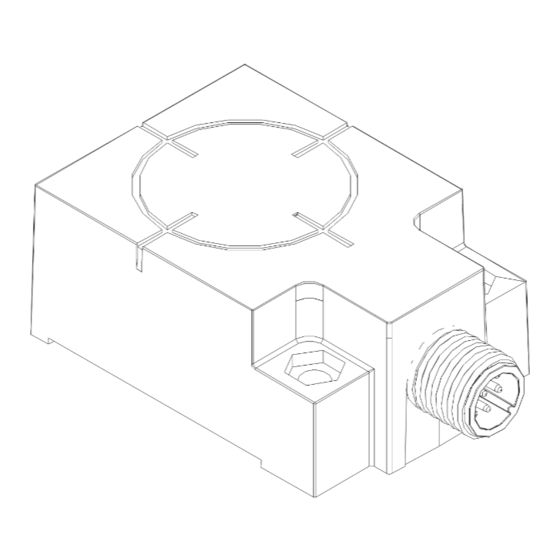
Attach the controller to the mounting bracket using the two sets of M4 screws, washers
and nuts provided. Place the nuts in each of the hex-shaped recessed cavities at the rear of
the Unit.
2.
Align the mounting bracket with the two mounting holes on the controller, then insert both
M4 screws (with washers) into the controller from the underside and secure completely
using a standard Phillips #2 head screwdriver. Tighten screws to 0.7 Nm (6 lbs / inch)
±10%.
3.
Fasten the other end of the mounting bracket to your work area. The Unit may be mounted
horizontally or vertically, but should be aligned in such a manner that the LED indicators can
be seen during operation.
4.
Connect the 5-pin, female end of a Subnet16™ compatible cable to the 5-pin, male, M12
interface connector on the Unit. Connect the opposite end of this cable to an Subnet16
Gateway or Subnet16 Hub interface module. Connect the Gateway or Hub to a host
computer via Category 5E Ethernet cabling*.
5.
Turn the power supply ON. The green power LED on the unit will illuminate when power is
applied to the unit. The five amber colored Node LEDs, when lit, display the Node ID value
(in binary format from right to left) currently assigned to the RFID Controller.
Note: the factory default Node ID is Node 00 - in which case none of the amber Node LEDs
will be lit.
6.
To verify operations, download the TCP/IP version of the HF Dashboard Utility. The HF
Dashboard Utility allows Gateway / Hub users to configure and control their controllers and
send RFID commands for testing purposes.
*For more information regarding the installation of a Subnet16 Gateway or Subnet16 Hub,
refer to the Operator's Manual for each product.
Figure 1: Controller, Mounting Bracket and Hardware
Millimeters
[INCHES]
28
[1.10]
3
[0.13]
4.5
[0.18]
2X
57
[2.25]
7
2X
[0.27]
42
[1.65]
92
[3.63]
SLOT
19
5 X 16
[0.74]
[.2 X .63]
2X
SLOT
5 X 8
26
[.2 X .31]
[1.02]
Figure 2: Dimensions
56.2
[2.21]
40
[1.57]
HEX NUT RECESS
Ø4.5
7.2mm ACROSS FLATS
[Ø.18]
MOUNTING
Millimeters
HOLE 2X
[Inches]
24
[0.94] 14.3
[0.56]
Power Requirements
The Unit obtains power directly from the
network bus (multi-drop Subnet16) and
requires 10~30 V DC, 2.4 W (100 mA @
24 V DC, 1 Amp peak).
Cabling Part Numbers
CBL-1480-XX: Cable (5-pin, male M12 to
5-pin, female M12, ThinNet)
CBL-1481-XX: Cable (5-pin, male M12 to
5-pin, female M12, ThinNet)
(XX = C
L
M
)
ABLE
ENGTH IN
ETERS
Installation Guidelines
RFID devices can be negatively affected by the presence of metallic objects near its RF field.
Avoid mounting the unit within 5 cm (two inches) of metallic surfaces.
Locate the unit away from sources of EMI (electro-magnetic interference) and away from devices
that generate high ESD (electro-static discharge) levels.
Do not route the Unit's cables near unshielded cables or near wiring that is carrying high voltage or
high current (such as for motors or solenoids). Cross cables only at perpendicular intersections.
Use the included polycarbonate mounting bracket or a similar non-metallic bracket. The bracket is
provided to help reduce electrically conducted spurious noise by isolating the RFID controller from
metallic surfaces.
If multiple RFID controllers operating at the same frequency (13.56 MHz) are to be installed, maintain
a minimum distance of 20 cm (8 inches) between adjacent RF devices.
www.balluff.com
28
[1.10]
39.2
[1.54]
15.5
12.5
[0.61]
[0.49]
Figure 3: Interface Connector - Pinout
The Balluff RFID Controller has one 5-pin, male
M12 connector that is used for data and power.
5-Pin, Male M12
PIN 3: 0VDC
Interface Connector
(PWR GND)
PIN 4:
TX/RX+
PIN 2:
10~30VDC
PIN 5:
TX/RX-
PIN 1:
SIGNAL GND
Advertisement
Table of Contents

Subscribe to Our Youtube Channel
Related Manuals for Balluff BIS M-410-067-001-04-S92


Summary of Contents for Balluff BIS M-410-067-001-04-S92
- Page 1 The Unit obtains power directly from the Turn the power supply ON. The green power LED on the unit will illuminate when power is The Balluff RFID Controller has one 5-pin, male network bus (multi-drop Subnet16) and applied to the unit. The five amber colored Node LEDs, when lit, display the Node ID value M12 connector that is used for data and power.
- Page 2 BIS M-410-067-001-04-S92 (C0405-485-01) RFID 3 0VDC CBL-1480-XX TX/RX+ CBL-1481-XX 10~30VDC TX/RX- www.balluff.com...
- Page 3 BIS M-410-067-001-04-S92 (C0405-485-01) RFID 3: 0VDC CBL-1480-XX: TX/RX+ CBL-1481-XX: 10~30VDC TX/RX- www.balluff.com...
- Page 4 BIS M-410-067-001-04-S92 56.2 (C0405-485-01) [2.21] RFID [1.57] [1.10] Ø4.5 7.2 mm [Ø.18] 0.7 Nm (6 39.2 [1.54] [0.94] 15.5 Subnet16™ 14.3 12.5 [0.61] [0.56] [0.49] Subnet16 RFID Subnet16) 10 30 V DC 2.4 W (100 mA @ 24 V DC 1...
Need help?
Do you have a question about the BIS M-410-067-001-04-S92 and is the answer not in the manual?
Questions and answers