Balluff SmartVision BAE PD-VS-014-05 User Manual
Hide thumbs
Also See for SmartVision BAE PD-VS-014-05:
- User manual (86 pages) ,
- User manual (49 pages)
Table of Contents
Advertisement
Quick Links
Advertisement
Table of Contents

Subscribe to Our Youtube Channel
Related Manuals for Balluff SmartVision BAE PD-VS-014-05


Summary of Contents for Balluff SmartVision BAE PD-VS-014-05
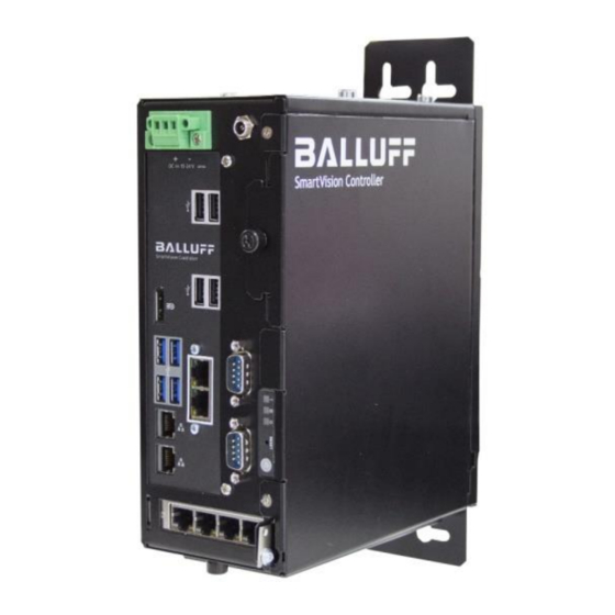
- Page 1 BAE PD-VS-014-05 SmartVision Controller...
-
Page 3: Table Of Contents
Gigabit Ethernet Status LED ................24 3.6.3 Cleaning ......................24 FIRST STEPS Step 1: Establishing a network connection with the Balluff SmartVision Controller ........................25 Step 2: Switching on the Balluff SmartVision Controller ....... 25 4.2.1 Connecting the DC power supply (19 to 28 V) via terminal clamp ....25 Step 3: Opening the BVS Cockpit software ............. - Page 4 BAE PD-VS-014-05 STARTUP Updating software ....................29 Updating Balluff Camera firmware ..............30 Network topologies .................... 31 5.3.1 Bandwidth limit of switches (multi-camera operation with Gigabit Ethernet) . 31 System settings ....................32 5.4.1 Adapting the network settings ................ 33 5.4.2...
-
Page 5: User Instructions
Vision as well as USB3 Vision compliant industrial cameras like the Balluff Camera BVS CA to the Balluff SmartVision Controller and operate them simultaneously. The manuals for the BVS Cockpit and the Balluff Camera BVS CA are available in the product download area on the Balluff product website via www.balluff.com The Balluff SmartVision Controller is an inspection system for automated industrial environments. -
Page 6: Parameters
BAE PD-VS-014-05 1.3.4 Parameters Parameters are shown in italics (e.g. CRC_16). 1.3.5 Directory paths Projekt:\Data Types\Benutzerdefin- Path information for saving data is shown with fixed font width (e.g. iert 1.3.6 ASCII code Characters transmitted in ASCII code are set in apostrophes (e.g. 'L'). 1.3.7 Symbols NOTE... -
Page 7: Abbreviations
Commercial duplications, re- productions, modifications and disseminations of any type require the prior written approval of Balluff GmbH. All infor- mation and notes in these operating instructions, particularly the chapter Safety Instructions, must be observed. -
Page 8: Legal Requirements
Balluff GmbH is authorized – but not obligated – to make updates or upgrades of the firmware available via the website of Balluff GmbH or in any other form. In such a case, Balluff GmbH is authorized – but not obligated – to inform you about the updates or upgrades. -
Page 9: Safety
Do not switch off the earth to ensure protection against electric shock or property damage. This system can be connected to an IT power supply. In any case, ensure that your Balluff SmartVision Controller is also connected to the mass. -
Page 10: Safety Notes For Assembly
Mechanical load - The Balluff SmartVision Controller assembly should be carried out in such a way that there are no hazardous operational conditions in the event of uneven mechanical loads. -
Page 11: Repairs
Information as to which system expansions are suitable for installation can be obtained from the technical customer service or from your outlet. The warranty is void if you cause defects to the Balluff SmartVision Controller due to installing or replacing system ex- pansions. -
Page 12: Maintenance
BAE PD-VS-014-05 2.2.7 Maintenance Replace CMOS (CR2032) battery Batteries are consumables and should be replaced every 3 years in order to ensure PC functionality. Please check the following prior to replacing WARNING Risk of explosion if battery is replaced by an incorrect type. Dispose of used batteries ac- cording to the instructions. -
Page 13: Disposal
This product is covered by WEEE Directive 2012/19/EU on waste electrical and electronic equipment. Dispose of the product properly and not as a part of the regular waste stream. The regulation of the re- spective country are to be observed. Information is provided by the national authorities. www.balluff.com... -
Page 14: Product Description
The Balluff SmartVision Controller is an inspection system, which application areas are optical identifications, inspections for quality assurance, and the measurement of objects. With the LAN interfaces you can integrate the Balluff SmartVision Controller into an existing network. Additionally, the Balluff SmartVision Controller offers two fieldbus connectors. Via USB 3.0 and Gigabit Ethernet ports you can connect USB3 Vision and GigE Vision compliant industrial cameras. -
Page 15: Product Variants
BAE PD-VS-014-05 Product variants The Balluff SmartVision Controller is developed according to the latest industrial standards: Intel® Core i7-6700TE Chipset Intel® Q170 Chipset iAMT 11.0 Memory 16 GB DDR4 Graphics Intel® HD graphics 530 1x 256GB 2,5“ SATA SSD (changeable via tray) Drives 2x Gigabit Ethernet (Intel®... -
Page 16: Transport
If you notice any transport damage or any irregularities, then please inform us. 3.2.3 Identification data of the device The Balluff SmartVision Controller can be identified clearly in case of necessary repairs thanks to the identification data. Furthermore, the MAC addresses of the LAN connectors are noted:... -
Page 17: Ambient And Environmental Conditions
Consider the climate and mechanical environmental conditions in the system features. • The Balluff SmartVision Controller was designed for use in a normal industrial environment. Without additional measures (supply of clean air), you cannot use the Pyramid IPC in places with difficult operational conditions due to corrosive vapours or gases. -
Page 18: Wall Mount
Mounting via mounting bracket Use the supplied mounting bracket (see gray area below). First, fasten the bracket on the back of the Balluff SmartVision Controller using 4 supplied screws. Use the additional 2 screws, to mount the Balluff SmartVision Controller at a wall. -
Page 19: Mounting Via Profile Rail (Only If The Rail Is Pre-Assembled)
Mounting via profile rail (only if the rail is pre-assembled) Use the supplied profile rail (see image below) and assemble it on the back of the Balluff SmartVision Controller. The profile rail can be assembled vertically or horizontally. Afterwards, you can mount the Balluff SmartVision Controller in a control cabinet. -
Page 20: Product Specification
BAE PD-VS-014-05 Product specification 3.4.1 Mechanical data Housing material Sheet steel galvanised; powder coated black Degree of protection IP20 Weight approx. 2.7 kg Dimensions (W × D × H) 216 x 191 x 88 mm... -
Page 21: Electrical Data
19V to 28V DC Max. current consumption without external load 85 W WARNING The Balluff SmartVision Controller and accessories must be supplied by Limited Power Source (LPS) according to UL/IEC 60950-1 or Class 2 source according to UL 1310. 3.4.3 Operating conditions Ambient temperature 10 to 50 °C / 10 to 80 % relative humidity... -
Page 22: Connections And Control Elements
Gound Chassis ground Hard drive caddy For changing SSD hard drives Front panel with power switch Status display of the Balluff SmartVision Controller and power switch to turn the and status LEDs Balluff SmartVision Controller on and off... -
Page 23: Display Elements
Power switch does not disconnect the equipment from the grid! WARNING If you keep the switch held down for more than 4 seconds during operation, then the system executes a forced shut-down; data may be lost in the process. www.balluff.com... -
Page 24: Gigabit Ethernet Status Led
3.6.3 Cleaning The outside of the Balluff SmartVision Controller Camera can be cleaned with a soft cloth. Persistent dirt can be removed with a cloth that is first moistened with a soap solution and wrung out. → After wiping off the dirt spots, wipe the camera with a dry cloth. -
Page 25: First Steps
BAE PD-VS-014-05 4 First steps Three simple steps are required to initially start up and configure the Balluff SmartVision Controller. Besides the Balluff SmartVision Controller, the following is required: • 24 V power supply with cold-device cable • LAN cable •... -
Page 26: Step 3: Opening The Bvs Cockpit Software
Connect the DC supply (screw terminal). Step 3: Opening the BVS Cockpit software Industrial cameras connected to the Balluff SmartVision Controller are being configured via the BVS Cockpit. This web interface is being opened and operated via web browsers. The following commercially available web browser are being supported: •... - Page 27 • press Windows + R and enter the address of the Balluff SmartVision Controller (e.g. \\svc-000110\). As soon as you have chosen a Balluff SmartVision Controller, the shared folders of the Balluff SmartVision Controller are displayed: •...
-
Page 28: Setting Up A Camera
To configure an industrial camera, start BVS Cockpit and select in the action menu "Configuration" the "Set up cam- era" tool. NOTE More information about the configuration interface of the BVS Cockpit can be found in the software manual ("BVS Cockpit Manual") on the Balluff website. -
Page 29: Startup
BAE PD-VS-014-05 5 Startup Updating software The Balluff website regularly offers new software updates on our website. The updates contain bug fixes, performance optimization, or functional extensions. NOTE We recommend updating the SmartVision Controller from time to time to derive maximum benefit from the SmartVision Controller. -
Page 30: Updating Balluff Camera Firmware
BAE PD-VS-014-05 Updating Balluff Camera firmware If the Balluff SmartVision Controller software was updated, you can update the firmware of connected Balluff Cameras. Insert the address or URL of the Balluff SmartVision Controllers. Select in the action menu "Configuration" the tool "Set up camera". -
Page 31: Network Topologies
The interaction of the industrial cameras with the system and the analyzing of a control is done via the digital I/Os; the interaction of the Balluff SmartVision Controller via the Gigabit Ethernet (LAN) conntector or the fieldbus. This allows, e.g. to initiate the trigger or query the status of the Balluff SmartVision Controller or the industrial camera. -
Page 32: System Settings
Webmin supports the browsers Chrome, Firefox, Opera, Safari, and Edge. Open a browser and enter the address or URL of the Balluff SmartVision Controller adding port 10000 at the end. This address can look like this: "https://svc-000110:10000/". Please take care of the "https", because it is a secured connection. -
Page 33: Adapting The Network Settings
By default, the Gigabit Ethernet (LAN) female connector 1 (internally mentioned as enp0s31f6) is set to get the IP ad- dress automatically assigned during the boot process via DHCP. By default, the second Gigabit Ethernet (LAN) con- nector is configured with 192.168.82.83/255.255.255.0. www.balluff.com... -
Page 34: Setting The System Time
BAE PD-VS-014-05 Via the tab "Active Now" you reach the overview of the current network values. The four Gigabit Ethernet (industrial cameras) female conntectors have a fixed IP from 192.168.200.1 to 192.168.203.1. Each connector has its own DHCP server. If you connect a GigE Vision industrial camera, which is set to get an IP ad- dress assinged via DHCP, will get an IP address automatically. -
Page 35: Selecting The Communication Interface For The Process Data
The communication interface is set in the System settings under Mode on the Communication tab. Available options for the selection are Fieldbus, TCP and UDP. If TCP or UDP is selected, the camera uses port 36701. The controlling sys- tem can use any available port. Interfaces that are not selected are deactivated! www.balluff.com... -
Page 36: Lan Interface
BAE PD-VS-014-05 LAN Interface The data are transferred as TCP or UDP packets via the LAN interface. For each instance following ports are used: Instance Port 36701 36702 36703 36704 5.6.1 LAN parameters in BVS Cockpit To communicate via UDP, you have to set the Mode in the system menu ("System settings -> communication") to "UDP". To communicate via TCP, this Mode must be set to "TCP". -
Page 37: Fieldbus Interfaces
The Communication tab contains various parameters to choose from depending on the fieldbus selected. 5.7.2 PROFINET fieldbus The communication between the Balluff SmartVision Controller and the host system is done via PROFINET IO. The system PROFINET IO consists of the following components: •... - Page 38 Process data of 4th instance at port 9003 Integration into Project Planning Software The connection of a Balluff SmartVision Controller to a Siemens S7 controller is shown with the “Siemens TIA Portal”. The exact procedure depends on the project planning software used.
- Page 39 Click on [Install]. ⇒ The GSDML file is being installed. ⇒ A message appears once the process has finished. Confirm the message and close the window. Select the dialog "Devices & networks". ⇒ The devices are displayed in the product tree. www.balluff.com...
- Page 40 BAE PD-VS-014-05 Adding a PROFINET device The devices are located in the hardware catalog under “Other field devices”, “Ident systems”, "Balluff Vision Solutions", "SmartVision Controller". The module is added as PROFINET IO. Open the dialog "Devices & networks". Select "Network view".
- Page 41 Configuring Balluff SmartVision Controller data The number of process data (buffer size) of the Balluff SmartVision Controller can be selected by deleting or inserting a corresponding module (min. 16 bytes, max. 512 bytes). For each used camera instance, a IO module has to be pro- jected.
- Page 42 BAE PD-VS-014-05 PROFINET parameters in BVS Cockpit The fieldbus parameters are set in the System settings on the "Communication" tab. PROFINET is preselected by de- fault. The fieldbus can be changed at any time between PROFINET and EtherNet/IP. NOTE After switching the fieldbus and after setting a few fieldbus parameters, an internal restart of the fieldbus module is necessary.
-
Page 43: Ethernet/Ip Fieldbus
5.7.3 EtherNet/IP fieldbus Device master data To parameterize the correct Balluff SmartVision Controller model in an EtherNet/IP network, device database information in the form of an EDS file is required. The file is located on the Balluff homepage (see www.balluff.com). - Page 44 BAE PD-VS-014-05 Integration in Rockwell Studio 5000 This example shows how the Balluff SmartVision Controller connected to a CompactLogix or ControlLogix PLC. Start EDS Hardware Installation Tool in the Logix Designer and register EDS file. Right-click Ethernet on the corresponding scanner card. Select a new module. Note: The function is not available in...
- Page 45 BAE PD-VS-014-05 Select Balluff SmartVision Controller Module BAE PD-VS and apply to the configuration. The input, output and configuration tags are automatically created in the controller tags. www.balluff.com...
- Page 46 BAE PD-VS-014-05 Set the desired IP address and connection parameters for the Balluff SmartVision Controllers under Module Proper- ties.
- Page 47 Setting and Displays Description IP mode IP address, subnet mask and gateway can either be manually set (static) or automatically using DHCP protocol or BOOTP. IP address Fieldbus IP Address Subnet mask Fieldbus subnet mask Gateway Fieldbus default gateway www.balluff.com...
-
Page 48: Appendix
BAE PD-VS-014-05 6 Appendix Troubleshooting Table Error Cause Action Accessing the Your Windows 10 installation does not allow a Update BVS Cockpit to a version > 2.3.0, which al- shared folders guest access to the shared folders (BVS Cock- lows accessing the shared folders with following is not possible. -
Page 49: Type Code
BAE PD-VS-014-05 Type code Balluff Accessory Equipment Programming Device Vision Solution 11-13 SmartVision Controller 15-16 Operating System Linux www.balluff.com...
Need help?
Do you have a question about the SmartVision BAE PD-VS-014-05 and is the answer not in the manual?
Questions and answers