Advertisement
BIS M-410-068-001-00-S115
(C0405-232-01)
Installation Guide
Installing the RFID Controller
1.
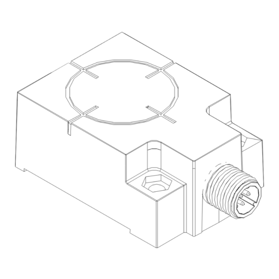
Attach the controller to the mounting bracket using the two sets of M4 screws, washers
and nuts provided. Place the nuts in each of the hex-shaped recessed cavities at the rear of
the Unit.
2.
Align the mounting bracket with the two mounting holes on the controller, then insert both
M4 screws (with washers) into the controller from the underside and secure completely
using a standard Phillips #2 head screwdriver. Tighten screws to 0.7 Nm (6 lbs / inch)
±10%.
3.
Fasten the other end of the mounting bracket to your work area. The Unit may be mounted
horizontally or vertically, but should be aligned in such a manner that the LED indicators can
be seen during operation.
4.
Connect the 8-pin, female M12 connector from your serial interface cable (CBL-1478) to
the 8-pin, male M12 connector on the Unit.
5.
Connect the 9-pin, female D-sub connector on the serial interface cable to a COM port on
the host computer. Tighten the cable's two locking thumbscrews.
6.
Connect the 2.5 mm DC power plug on the power supply transformer to the DC power
jack receptacle on the serial interface cable. Tighten the locking ring to prevent power from
becoming disconnected during use. The Controller requires a power supply capable of
providing 10~30 V DC, 2.4 W (100 mA @ 24 V DC).
7.
Plug the power supply transformer into a suitable AC power source. Apply power to the
controller after all cable connections have been made. The LEDs on the unit will flash.
8.
On the host computer, set COM port parameters to: 9600 baud, 8 data bits, 1 stop bit,
no parity and no handshaking.
9.
To verify operations, download the serial version of the HF Dashboard Utility. The HF
Dashboard Utility allows users to configure and control their controllers and send RFID
commands for testing purposes.
Figure 1: Controller, Mounting Bracket and Hardware
Millimeters
[INCHES]
28
[1.10]
3
[0.13]
4.5
[0.18]
2X
57
[2.25]
7
2X
[0.27]
42
[1.65]
92
[3.63]
SLOT
19
5 X 16
[0.74]
[.2 X .63]
2X
SLOT
5 X 8
26
[.2 X .31]
[1.02]
Figure 2: Dimensions
56.2
[2.21]
40
[1.57]
HEX NUT RECESS
Ø4.5
7.2mm ACROSS FLATS
[Ø.18]
MOUNTING
Millimeters
HOLE 2X
[Inches]
24
[0.94] 14.3
[0.56]
Power Requirements
The Unit requires an electrical supply
voltage of 10~30 V DC and has a power
draw of 2.4 W (100 mA @ 24 V DC,
1 Amp peak). Use a regulated power
supply that is capable of delivering these
requirements.
Cabling Part Numbers
CBL-1478: Cable Assembly (8-pin, female
M12 to RS232; with 2.5 mm DC power
jack, 2 m)
CBL-1488-XX: Cable (8-pin, female M12
to bare wire leads)
CBL-1492-XX: Cable (8-pin, right-angle
female M12 to bare wire leads)
CBL-1493: Connector (8-pos, straight
female M12, field mountable)
(XX = C
L
M
)
ABLE
ENGTH IN
ETERS
Installation Guidelines
RFID devices can be negatively affected by the presence of metallic objects near its RF field.
Avoid mounting the unit within 5 cm (two inches) of metallic surfaces.
Locate the unit away from sources of EMI (electro-magnetic interference) and away from devices
that generate high ESD (electro-static discharge) levels.
Do not route the Unit's cables near unshielded cables or near wiring that is carrying high voltage or
high current (such as for motors or solenoids). Cross cables only at perpendicular intersections.
Use the included polycarbonate mounting bracket or a similar non-metallic bracket. The bracket is
provided to help reduce electrically conducted spurious noise by isolating the RFID controller from
metallic surfaces.
If multiple RFID controllers operating at the same frequency (13.56 MHz) are to be installed, maintain
a minimum distance of 20 cm (8 inches) between adjacent RF devices.
www.balluff.com
28
[1.10]
39.2
[1.54]
15.5
12.5
[0.61]
[0.49]
Figure 3: Interface Connector - Pinout
The Balluff RFID Controller has one 8-pin, male
M12 connector that is used for data and power.
8-Pin, Male M12
Interface Connector
PIN 4:
N/C
PIN 5:
N/C
PIN 3:
N/C
PIN 6:
RX
PIN 2:
0VDC
PIN 7:
(PWR GND)
TX
PIN 1:
PIN 8:
10~30VDC
SIGNAL GND
N/C = Not Connected
Advertisement
Table of Contents

Subscribe to Our Youtube Channel
Related Manuals for Balluff BIS00W2


Summary of Contents for Balluff BIS00W2
- Page 1 Tighten the cable’s two locking thumbscrews. The Unit requires an electrical supply The Balluff RFID Controller has one 8-pin, male Connect the 2.5 mm DC power plug on the power supply transformer to the DC power voltage of 10~30 V DC and has a power M12 connector that is used for data and power.
- Page 2 [0.18] 10~30VDC XX = N/C = [1.10] RFID [2.25] 5 cm (2 in) [0.27] [1.65] [3.63] 5 X 16 [0.74] [0.2 X 0.63] RFID [0.13] 5 X 8 [0.2 X 0.31] [1.02] RFID (13.56 Mhz) 20 cm (8 in) www.balluff.com...
- Page 3 15.5 [0.94] 14.3 12.5 [0.61] [0.56] [0.49] D-sub 2.5mm DC 10~30V DC, 2.4W(100mA @ 24V DC) 10~30V DC Balluff RFID 2.4W(100mA @ 24V DC, 1Amp 9600 . HF RFID CBL-1478: M12 - RS232, 2.5mm DC 2 m) CBL-1488-XX: M12 -...
- Page 4 10 30VDC N/C = [0.18] RFID 5 cm (2 [1.10] EMI ( ESD ( [2.25] [0.27] [1.65] [3.63] 5 X 16 [0.74] [0.2 X 0.63] RFID [0.13] (13.56 MHz) RFID 5 X 8 20 cm (8 [0.2 X 0.31] [1.02] www.balluff.com...
Need help?
Do you have a question about the BIS00W2 and is the answer not in the manual?
Questions and answers