Crestron FlipTop FT2 Series Quick Start
Cable management system, 202 size, electrical
Hide thumbs
Also See for FlipTop FT2 Series:
- Quick start manual (11 pages) ,
- Quick start (2 pages) ,
- Manual (2 pages)
Table of Contents
Advertisement
Quick Links
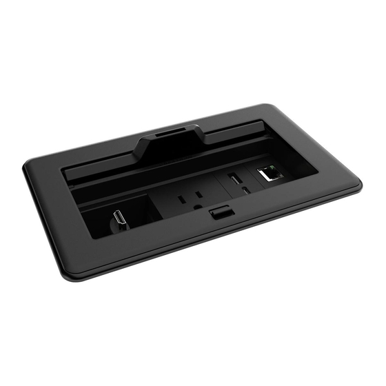
FT2-202-ELEC
FlipTop™ Cable Management System FT2 Series, 202 Size, Electrical
The Crestron® FT2-202-ELEC FlipTop™ cable management assembly
installs into a table or other horizontal surface to provide modular
tabletop connectivity for users. The one-touch lid on the unit conceals
six module spaces arranged in a single row.
The FlipTop assembly includes four pass-through cable modules
and two blank plate modules. Each pass-through cable module
accommodates a Crestron FT2A-CBL-PT Series Pass-Through Cable
(not included) and various other third-party interface cables. Use blank
plate modules to cover any unused module spaces within the FlipTop
assembly. An included power pack, power supply holder, and power
cord energize the power bus located within the FlipTop assembly.
The flexible modular design of the FlipTop assembly can be customized
with an assortment of Crestron accessories (not included):
•
FT2A-CBL-PT is a series of pass-through cables optimized for
the provided pass-through cable modules.
•
FT2A-CBLR-GR is a series of gravity cable retractors. Each cable
in the retractor pulls out up to 3 ft (0.9 m) and retracts gently
back into the FlipTop assembly.
•
FT2A-CBLR-1T is a series of one-touch cable retractors. Each
cable in the retractor pulls out up to 5 ft (1.5 m) and retracts
when the cable retractor button is pressed or a Crestron control
system automatically retracts the cable.
•
FT2A-CP is a series of active connector plate modules. Each
module provides panel mounted connectors, which allow the
connection of devices using separate, detached interface cables
(not included).
•
FT2A-CHGR-USBA/C is a USB rapid charging module. It provides
one USB Type-C™ charging port and one USB Type-A charging
port.
•
FT2A-PWR-US is a series of AC power outlet modules that
provide one or more NEMA 5 type receptacles above the table.
The basic model provides one additional outlet below the table;
the other models provide two.
•
FT2A-UTK-SHELF is an under-table utility shelf capable of
holding HDMI® switches or HDBaseT® transmitters.
•
FT2A-PLT-BLANK-10 is a pack of 10 blank plate modules used
to supplement those provided with the FlipTop assembly. Each
module covers one unused module space within the assembly.
•
FT2A-PLT-PT-10 is a pack of 10 pass-through cable modules used
to supplement those provided with the FlipTop assembly. Each
module accommodates a Crestron FT2A-CBL-PT Series Pass-
Through Cable or a third-party interface cable.
NOTE:
For more information about FlipTop assembly
accessories, refer to the specific product manual located at
www.crestron.com/manuals.
Check the Box
Item
FT2-202-ELEC
Bars, Locking, with Screws (P/N 4528298)
Connector, 3-Pin (P/N 2003575)
Holder, Power Supply (P/N 2048887)
Module, Blank Plate (P/N 2049602)
Module, Pass-Through Cable (P/N 4526880)
Power Cord, 5 ft 10 in. (1.78 m) (P/N 2042043)
Power Pack, 24 Vdc, 2.5 A, 100-240 Vac (P/N 2045873)
Template, Cutout (P/N 4529443)
FT2-202-ELEC-AL Only
Bezel, FT2-202, Alloy (P/N 4528297)
FT2-202-ELEC-B Only
Bezel, FT2-202, Black (P/N 4528296)
Mount the FlipTop Assembly
The next two sections describe the mounting procedure.
Cut the Mounting Hole
NOTE:
Before cutting the mounting hole, check underneath the table
for any obstructions that may impede the installation of the FlipTop
assembly, retractors, and accessories.
1.
Trace an outline of the mounting hole onto the table using the
included cutout template.
2.
Cut a mounting hole in the table with an appropriate saw.
Secure the FlipTop Assembly
To secure the FlipTop assembly:
1.
Ensure that the two swiveling dogs are positioned inside of
the FlipTop assembly, and then insert the assembly into the
mounting hole until the top lip is flush with the table surface.
CAUTION:
Set the screwdriver torque to its lowest setting to
avoid stripping the swiveling dogs and damaging the table.
If removing the FlipTop assembly from the table, ensure that
the screwdriver rotation is set correctly before loosening the
swiveling dogs.
2.
Carefully tighten the two swiveling dogs in the FlipTop assembly
clockwise until the assembly is secured in place against the table.
Do not overtighten the swiveling dogs.
Location of Swiveling Dogs
Swiveling
Retractable
FlipTop
dogs (2)
lid
assembly
Connect the FlipTop Assembly
Access the network connector and power bus barrel jack on the
Qty
underside of the FlipTop assembly.
1
Location of 3-Pin Network Connector and Power Bus Barrel Jack
2
FlipTop
3-Pin
assembly
1
network
(bottom
Power bus
connector
view)
barrel jack
1
2
4
1
1
1
1
Network Connection
1
A network connection between the FlipTop assembly and a Crestron
control system or DMPS3 enables remote control of installed
accessories. For example, when a networked FlipTop assembly with
a one-touch cable retractor is installed in a room with an occupancy
sensor and the sensor detects an unoccupied room, the FlipTop
assembly communicates with the system to automatically retract the
cable.
Connect the FlipTop assembly to a Crestron control system or DMPS3
via the 3-pin connector using standard Cresnet® cable. The red power
lead is not connected and should be terminated.
3-Pin Connector with Wires Attached
White (Y)
Blue (Z)
Black (G)
Power Supply Connection and Placement
The FlipTop assembly ships with one 24 Vdc power supply that is used
to supply power to the power bus in the assembly. There are four
possible locations to attach the power supply. Connect the power
supply prior to installing any modules.
To connect the power supply to the power bus.
1.
Underneath the table, connect the power supply to the bottom
of the power bus.
2.
Dress the power cord.
3.
Slide the power supply into the power supply holder until it is
secured in place.
4.
Insert the power supply holder into the side of the FlipTop
assembly so that the four mounting posts on the rear of the
holder engage the four rectangular slots in one of the four
mounting locations.
Quick Start
Location of Power Supply
Power
Power
Rectangular
FlipTop
supply
supply
slots (4)
assembly
holder
5.
Slide the holder downward until it is secured to the FlipTop
assembly.
Mounting Locations of Power Supply
Power supply
mounting locations (4)
6.
Connect the included 5 ft 10 in. (1.78 m) power cord to the power
jack on top of the power supply, and then connect the other end
to a power source. Do not apply power until all modules have
been installed and all connections have been made to the FlipTop
assembly.
Advertisement
Table of Contents

Subscribe to Our Youtube Channel
Related Manuals for Crestron FlipTop FT2 Series


Summary of Contents for Crestron FlipTop FT2 Series
- Page 1 Bezel, FT2-202, Alloy (P/N 4528297) cable in the retractor pulls out up to 5 ft (1.5 m) and retracts Network Connection when the cable retractor button is pressed or a Crestron control FT2-202-ELEC-B Only system automatically retracts the cable. Bezel, FT2-202, Black (P/N 4528296) A network connection between the FlipTop assembly and a Crestron •...
- Page 2 CE marking. and used in accordance with the instructions, may cause harmful interference to radio proprietary interest in the marks and names of others. Crestron is not responsible for errors in The product warranty can be found at www.crestron.com/warranty.
Need help?
Do you have a question about the FlipTop FT2 Series and is the answer not in the manual?
Questions and answers