Table of Contents
Advertisement
Quick Links
Advertisement
Table of Contents

Related Manuals for TRENDnet TEW-673GRU


Summary of Contents for TRENDnet TEW-673GRU
-
Page 2: Federal Communication Commission Interference Statement
Federal Communication Commission Interference Statement This equipment has been tested and found to comply with the limits for a Class B digital device, pursuant to Part 15 of the FCC Rules. These limits are designed to provide reasonable protection against harmful interference when the equipment is operated in a commercial environment. - Page 3 This d device compl lies with the essential req been applied in o order to pro ove presump 1999/ 5/EC: EN60 950-1: 2006 Safety y of Informat ion Technolo ogy Equipme EN 50 0385: 2002 Produ uct standard to demons strate the c teleco ommunication...
- Page 4 übrigen einsc nitab TREND Dware sead dme TEW-67 metatud direkt tiivist tuleneva atele teistele a ware declares s that this TEW-673GRU other relevant provisions of f Directive 199 presente TRE ENDware dec clara que el squiera otras d disposiciones a aplicables o ex ΥΣΑ...
-
Page 5: Table Of Contents
TABLE OF CONTENT BOUT UIDE Purpose ... 1 Terms/Usage ... 1 Overview of this User’s Guide ... 1 ... 2 NTRODUCTION Applications: ... 2 Supported Features: ... 3 NPACKING AND ETUP Unpacking ... 4 Setup ... 4 Wireless Performance Considerations ... 5 ARDWARE NSTALLATION Front Panel and Top Panel ... - Page 6 Dynamic ... 41 Routing Table... 41 Access ... 43 Filter ... 43 Virtual Server ... 46 Special AP ... 47 DMZ... 48 Firewall Settings ... 49 QoS ... 50 Management ... 51 Remote Management ... 51 Tools ... 52 Restart ... 52 Settings ...
-
Page 7: About This Guide
ABOUT THIS GUIDE Congratulations on your purchase of this 300Mbps Wireless N Dual Band Gigabit Router with USB Port. This integrated access device combines Internet gateway functions with wireless LAN and Fast Ethernet switch. It provides a complete solution for Internet surfing and office resource sharing, and it is easy to configure and operate for every user. -
Page 8: Introduction
INTRODUCTION 300Mbps Concurrent Dual Band Wireless N Gigabit Router The 300Mbps Concurrent Dual Band Wireless N Gigabit Router (model TEW- 673GRU) delivers unsurpassed Dual Band wireless speed, coverage, and reliability with up to 14x the speed and 6x the coverage of a wireless g connection*. Concurrent Dual Band technology creates two separate 300Mbps wireless n networks at the same time—one on the 2.4GHz frequency and the other on the less congested 5GHz frequency. -
Page 9: Supported Features
Supported Features: Compliant with IEEE 802.11n/g/b/a standards Transmits simultaneous 2.4GHz and 5GHz Wireless Local Area Network (WLAN) signals (with separate default SSIDs) 4 x 10/100/1000Mbps Auto-MDIX LAN ports 1 x 10/100/1000Mbps WAN port (Internet) 2 x USB 2.0 ports 1 x Wi-Fi Protected Setup (WPS) button Color LCD management interface: view device status, local time, network performance, and additional router management options Compatible with most popular cable/DSL Internet Service Providers using... -
Page 10: Unpacking And Setup
Unpacking Open the box of the WLAN Router and carefully unpack it. The box should contain the following items: TEW-673GRU 300Mbps Wireless N Dual Band Gigabit Router with USB Port CD ROM (Utility/User’s Guide) Multi-Language Quick Installation Guide 2 x 2dBi gain dipole antenna Power Adapter (12V DC, 2A) Cat. -
Page 11: Wireless Performance Considerations
Wireless Performance Considerations There are a number of factors that can impact the range of wireless devices. 1. Adjust your wireless devices so that the signal is traveling in a straight path, rather than at an angle. The more material the signal has to pass through the more signal you will lose. -
Page 12: Hardware Installation
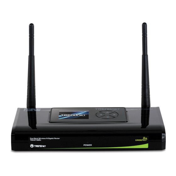
HARDWARE INSTALLATION Front Panel and Top Panel The figure below shows the front panel of the 300Mbps Wireless N Dual Band Gigabit Router with USB Port. Front Panel POWER LED: This indicator lights green when the hub is receives power, otherwise it is off. LCD Screen: The LED screen displays information regarding the router. -
Page 13: Rear Panel
Rear Panel The figure below shows the rear panel of the 300Mbps Wireless N Dual Band Gigabit Router with USB Port. Rear Panel Antenna: There are two 2dBi gain antennas on the rear panel for wireless connection. LAN (1-4): Four 10/100/1000Mbps Auto-MDIX LAN port for connecting 10Mbps, 100Mbps Ethernet or 10000Mbps Gigabit connections. -
Page 14: Side Panel
Side Panel The figure below shows the side panel of the 300Mbps Wireless N Dual Band Gigabit Router with USB Port. WPS (side panel): Push this button to execute the Wi-Fi Protected Setup process. -
Page 15: Hardware Connections
Hardware connections Connecting the WLAN Router 1. Plug in one end of the network cable to the WAN port of the WLAN Router. 2. Plug in the other end of the network cable to the Ethernet port of the xDSL or Cable modem. -
Page 16: Pc Network Tcp/Ip Setting
PC NETWORK TCP/IP SETTING The network TCP/IP settings differ based on the computer’s operating system (Win95/98/ME/NT/2000/XP) and are as follows. Windows 95/98/ME 1. Click on the “Network neighborhood” icon found on the desktop. 2. Click the right mouse button and a context menu will be show. 3. -
Page 17: Windows 2000
6. Select “None” for the “Gateway address” field. Windows 2000 Double click on the “My Computer” icon on the desktop. When “My Computer” window opens, open the “Control Panel” and then open the “Network dialup connection” applet. Double click on the “Local area network connection” icon. Select “Properties”... -
Page 18: Windows Xp / Vista
3. Set both “IP address” and “DNS” to Automatic configuration. Windows XP / Vista Point the cursor and click the right button on the “My Network Place” icon. Select “properties” to enter the TCP/IP setting window. 1. Set “IP address” to “Obtain an IP address automatically.” 2. -
Page 19: Configuration
CONFIGURATION First make sure that the network connections are functioning normally. This WLAN Router can be configured using Internet Explorer 6.0 or newer web browser versions. Login to the WLAN Router through Wireless LAN Before configuring the WLAN Router through WLAN, make sure that the SSID, Channel and the WEP is set properly. -
Page 20: Setup Wizard
Setup wizard is provided as part of the web configuration utility. Users can simply follow the step-by-step process to get the wireless Router configuration ready to run in 6 easy steps by clicking on` the “Wizard” button on the function menu. The following screen will appear. - Page 21 Step 3: Set LAN connection and DHCP server Set user’s IP address and mask. The default IP is 192.168.10.1. If the user chooses to enable DHCP, please click “Enable”. DHCP enabled is able to automatically assign IP addresses. Please assign the range of IP addresses in the fields of “Range start”...
- Page 22 Fixed IP Address: If the Internet Service Provider (ISP) assigns a fixed IP address, choose this option and enter the assigned WAN IP Address, WAN Subnet Mask, WAN Gateway Address and DNS Server Addresses for the WLAN Router. PPPoE to obtain IP automatically:...
- Page 23 If connected to the Internet using a PPPoE (Dial-up xDSL) connection, and the ISP provides a User Name and Password, then choose this option and enter the required information. PPPoE with a fixed IP address: If connected to the Internet using a PPPoE (Dial-up xDSL) connection, and the ISP provides a User Name, Password and a Fixed IP Address, choose this option and enter the required information.
- Page 24 PPTP: If connected to the Internet using a PPTP xDSL connection, enter your IP, Subnet Mask, Gateway, Server IP, PPTP Account and PPTP Password.
- Page 25 L2TP: If connected to the Internet using a L2TP (Dial-up xDSL) connection and the ISP provides a Server IP, Account and Password information, choose this option and enter the required information.
- Page 26 Big Pond Cable(Australia): If your ISP is Big Pond Cable, the ISP will provide a User Name, Password, Authentication Server and Login Server IP (Optional). Choose this option and enter the required information. Russia PPPoE: If your ISP is Russian PPPoE, the ISP will provide a User Name, Password. If you have a Static IP WAN Physical IP Address, WAN Physical Subnet Mask and WAN...
- Page 27 Physical Gateway IP Address will be required. Choose this option and enter the required information. Russia PPTP: If connected to the Internet using Russian PPTP xDSL connection, enter your server IP, PPTP Account and Password. If using Static IP you must enter your IP, Subnet Mask, Gateway, Server IP, PPTP Account and PPTP Password.
- Page 28 If connected to the Internet using Russian L2TP (Dial-up xDSL) enter your server IP, PPTP Account and Password. If using Static IP you must enter your IP, Subnet Mask, Gateway, Server IP, PPTP Account and PPTP Password.
- Page 29 Step 5: Set Wireless LAN connection Click “Enable” to enable Wireless LAN. If user enables the Wireless LAN, type the SSID in the text box and select a channel. The SSID and channel must be the same as wireless devices attempting to connect to the WLAN Router. Step 6: Setup completed The Setup wizard is now completed.
-
Page 30: Main Configuration
Host Name: Type the host name in the text box. The host name is required by some ISPs. The default host name is "TEW-673GRU" IP Address: This is the IP address of the WLAN Router. The default IP address is 192.168.10.1. -
Page 31: Wan
End IP: Type an IP address to serve as the end of the IP range that DHCP will use to assign IP addresses to all LAN devices connected to the WLAN Router. Domain Name: Type the local domain name of the network in the text box. This item is optional. -
Page 32: Password
WAN IP: Select whether user wants to specify an IP address manually, or want to obtain an IP address automatically. When Specify IP is selected, type the IP address, subnet mask, and default gateway in the text boxes. User’s ISP will provide with this information. -
Page 33: Time
Time This screen enables users to set the time and date for the WLAN Router's real-time clock, select properly time zone, and enable or disable daylight saving. Local Time: Displays the current time applied on the WLAN Router. Time Zone: Select the time zone from the drop-down list. Synchronize the clock with: Select the clock adjustment method form the drop- down list. -
Page 34: Dynamic Dns
Dynamic DNS This synchronizes the DDNS server with your current Public IP address when you are online. First, you need to register your preferred DNS with the DDNS provider. Then, please select the DDNS address in the Server Address and fill the related information in the below fields: Host Name, User Name and Password. - Page 35 2.4GHz Enable/Disable: Enables or disables 2.4GHz wireless LAN on the WLAN Router. SSID: Type an SSID in the text box. The SSID of any wireless device must match the SSID typed here in order for the wireless device to access the LAN and WAN of the WLAN Router.
- Page 36 5GHz Enable/Disable: Enables or disables 5GHz wireless LAN on the WLAN Router. SSID: Type an SSID in the text box. The SSID of any wireless device must match the SSID typed here in order for the wireless device to access the LAN and WAN of the WLAN Router.
-
Page 37: Security
Security This page allows users to set the wireless security of the WLAN router for a secure wireless communication. Authentication Type: The authentication type is set to Disable by default. There are four options: Disabled, WEP, WPA, WPA2 and WPA-Auto. WEP Encryption... - Page 38 WEP: Open System and Shared Key requires the user to set a WEP key to exchange data with other wireless clients that have the same WEP key. Mode: Select the key type: ASCII or HEX WEP Key: Select the level of encryption from the drop-down list. The WLAN Router supports, 64 and 128-bit encryption.
- Page 39 1. Enter the IP address, Port used and Shared Secret by the Primary Radius Server. 2. Enter the IP address, Port used and Shared Secret by the Secondary Radius Server. (optional) WPA-PSK/WPA2-PSK Security If WPA, WPA2 or WPA-Auto PSK is selected the below screen will show. Cipher Type: Select the cipher type for TKIP or AES encryption, Select Auto for auto detects the cipher type.
-
Page 40: Advanced
Advanced This screen enables users to configure advanced wireless functions. Beacon Interval: Type the beacon interval in the text box. User can specify a value from 25 to 1000. The default beacon interval is 100. RTS Threshold: Type the RTS (Request-To-Send) threshold in the text box. This value stabilizes data flow. -
Page 41: Wifi Protected Setup
WIFI Protected Setup This screen enables users to configure the Wi-Fi Protected Setup function. WPS: Enable or Disable the WPS (Wi-Fi Protected Setup) function Status: Displays the state (Un-configured State/Configured State) information of WPS. Self-PIN Number: Display the default PIN number of the WLAN Router. Client PIN Number: Type Client PIN number that the client uses to negotiate with WLAN Router via WPS protocol. -
Page 42: Status
Status This selection enables users to view the status of the WLAN Router LAN, WAN and Wireless connections, and view logs and statistics pertaining to connections and packet transfers. Device Information This screen enables users to view the WLAN Router’s LAN, Wireless and WAN configurations. -
Page 43: Log
to view a list of client stations currently connected to the WLAN Router LAN interface. Click “DHCP Release” to release all IP addresses assigned to client stations connected to the WAN via the WLAN Router. Click “DHCP Renew” to reassign IP addresses to client stations connected to the WAN. -
Page 44: Log Setting
Log Setting This screen enables users to set Router Log parameters. SMTP Authentication: Select Enabled SMTP server authentication. SMTP Account: If the SMTP Authentication enabled, fill in the SMTP account name here. SMTP Password: If the SMTP Authentication enabled, fill in the password of the SMTP account here. -
Page 45: Statistic
Log Type: Enables users to select what items will be included in the log: System Activity: Displays information related to WLAN Router operation. Debug Information: Displays information related to errors and system malfunctions. Attacks: Displays information about any malicious activity on the network. Dropped Packets: Displays information about packets that have not been transferred successfully. -
Page 46: Wireless
Wireless This screen enables users to view wireless information about wireless devices that are connected to the WLAN Router. Connected Time: Lists all wireless clients and how long they have been connected WLAN Router. MAC Address: Displays the wireless client’s MAC address. Routing This selection enables users to set how the WLAN Router forwards data: Static and Dynamic. -
Page 47: Dynamic
Network Mask: Type the network (subnet) mask of the network. If this field is left blank, the network mask defaults to 255.255.255.0. Contact the ISP or network administrator for this information. Gateway Address: Type the gateway address of the network. Contact the ISP or network administrator for this information. - Page 48 Network Address: Displays the network IP address of the connected node. Network Mask: Displays the network (subnet) mask of the connected node. Gateway Address: Displays the gateway address of the connected node. Interface: Displays whether the node is connected via a WAN or LAN. Metric: Displays the metric of the connected node.
-
Page 49: Access
Access This page defines access restrictions, set up protocol and IP filters, create virtual servers, access for special applications such as games, and set firewall rules. Filter Using filters to deny or allow the users to access. Five types of filters to select: MAC, URL blocking, IP, Protocol filter and Domain blocking. - Page 50 Update: Click to update information for the user, if you have changed any of the fields. Delete: Select a user from the table at the bottom of the list and click Delete to remove the user profile. New: Click New to erase all fields and enter new information. Domain/URL Blocking You could specify the domains that allow users to access or deny by clicking one of the two items.
- Page 51 Protocol/IP Filters This screen enables you to define a minimum and maximum IP address range filter; all IP addresses falling within the range are not allowed Internet access. The IP filter profiles are listed in the table at the bottom of the page. (Note: Click anywhere in the item.
-
Page 52: Virtual Server
Virtual Server This screen enables users to create a virtual server via the WLAN Router. If the WLAN Router is set as a virtual server, remote users requesting Web or FTP services through the WAN are directed to local servers in the LAN. The WLAN Router redirects the request via the protocol and port numbers to the correct LAN server. -
Page 53: Special Ap
Special AP This screen enables users to specify special applications, such as games which require multiple connections that are blocked by NAT. The special applications profiles are listed in the table at the bottom of the page. Note: When selecting items in the table at the bottom, click anywhere in the item. The line is selected, and the fields automatically load the item's parameters, which user can edit. -
Page 54: Dmz
Add: Click to add the special application profile to the table at the bottom of the screen. Update: Click to update information for the special application if user have selected a list item and have made changes. Delete: Select a list item and click Delete to remove the item from the list. Cancel: Click Cancel button to erase all fields and enter new information. -
Page 55: Firewall Settings
Firewall Settings This screen enables users to set up the firewall. The WLAN Router provides basic firewall functions, by filtering all the packets that enter the WLAN Router using a set of rules. The rules are listed in sequential order--the lower the rule number, the higher the priority the rule has. -
Page 56: Qos
Priority Up: Select a rule from the list and click “Priority Up” to increase the priority of the rule. Priority Down: Select a rule from the list and click “Priority Down” to decrease the priority of the rule. Update Priority: After increasing or decreasing the priority of a rule, click “Update Priority”... -
Page 57: Management
Automatic Classification: This option is enabled by default. This will allow your router to automatically determine the network priority of running programs. Management Management enables users to set up the Remote Management feature. Remote Management This screen enables users to set up remote management. Using remote management, the WLAN Router can be configured through the WAN via a Web browser. -
Page 58: Tools
Tools This page enables users to restart the system, save and load different settings as profiles, restore factory default settings, run a setup wizard to configure WLAN Router settings, upgrade the firmware, and ping remote IP addresses. Restart Click “Restart” to restart the system in the event the system is not performing correctly. -
Page 59: Firmware
Load Settings: Click “Browse” and go to the location of a stored profile. Click “Load” to load the profile's settings. Restore Factory Default Settings: Click “Restore” to restore the default settings. All configuration changes will lost. Firmware This screen enables users to keep the WLAN Router firmware up to date. Please follow the below instructions: Download the latest firmware from the manufacturer's Web site, and save it to disk. -
Page 61: Using The Lcd Panel
USING THE LCD PANEL The LCD panel provides information on device, performance, settings, and helps to initiate WPS (Wi-Fi Protected Setup). Main Menu When turning on the router, the Welcome screen appears. After a few seconds, the Main Menu screen appears. Menu Device Info Performance... -
Page 62: Device Info Menu
Device Info Menu The Device Info menu provides information about the router, Internet, wireless, and wired connection, including hardware/firmware version, router uptime, WAN type, radio band, security, IP address, etc. To enter the Device Info menu, press ▼ to highlight the Device Info icon on the Main Menu screen. -
Page 63: Internet
Internet 1. To select Internet, press ▼ and ► to highlight Internet on the Device Info menu. 2. Press ▼ to enter the Internet screen. Information about WAN type, link status, cable status, and connected time are displayed. 3. To go back to the Device Info menu or the Main Menu screen, press ▲ repeatedly until the desired menu or screen is reached. -
Page 64: Wired
Wired 1. To select Wired, press ▼ and ► to highlight Wired on the Device Info menu. 2. Press ▼ to enter the Wired screen. Information about IP address, subnet, DHCP server, MAC address, and LAN status are displayed. 3. To go back to the Device Info menu or the Main Menu screen, press ▲ repeatedly until the desired menu or screen is reached. -
Page 65: Settings Menu
1. On the Performance menu, press ▼ and ► to highlight 2.4GHz, 5GHz, Wired, or Internet. 2. Press ▼ to enter the selected performance screen. Information about the data transfer rate is displayed. 3. To go back to the Performance menu, press ▲ twice. 4. -
Page 66: Restart
Restart 1. To select Restart, press ▼ to highlight Restart on the Settings screen. 2. Press ▼. A confirmation message appears. 3. Press ◄ or ► to select Yes or No. • Select Yes to restart the device. • Select No to return to the previous screen. 4. -
Page 67: Date/Time
Date/Time 1. To select Date/Time, press ▼ and ► to highlight Date/Time on the Settings menu. 2. Press ▼ to enter the Time/Date screen. 3. Information about date and time is displayed. 4. To go back to the Settings menu, press ▲ twice. 5. -
Page 68: Wps Menu
WPS Menu The WPS menu helps to initiate WPS (Wi-Fi Protected Setup). Step-by-step instructions are provided to go through the procedure. To enter the WPS menu, press ▼ and ► to highlight the WPS icon on the Main Menu screen. Two options are available: WPS and Current PIN. - Page 69 5. Press the WPS button of the router, which is located on the right side. 6. Press ▼ to go to the next step. NOTE: You have to wait for a few minutes to establish the connection. 7. If the connection succeeds, a success message appears. The Device IP and MAC address are displayed.
-
Page 70: Current Pin
Current PIN 1. To select Current PIN, press ▼ and ► to highlight Current PIN on the WPS menu. 2. Press ▼. A confirmation message appears. 3. Press ◄ or ► to select Yes or No: • Select Yes to refresh the PIN number. After few seconds, the new PIN number appears on the screen. -
Page 71: Usb Control Center Utility
WLAN Router. The utility allows you to use USB devices as if they were connected directly to your PC through the Wireless N Gigabit Router with USB port (TEW-673GRU). System Select this feature to completely close and exit from USB Control Center utility. -
Page 72: Configure Server
Configure Server Click this button to configure the USB server and to log into the user interface of the Wireless N Gigabit Router with USB port (TEW-673GRU). Print Sharing This section describes how to use a USB printer through the WLAN Router. Note: For proper installation it is recommended that the printer’s drivers are installed... -
Page 73: Network Scanner
Set Auto-Connect Printer Provides a list of installed printers on your computer. Select the printer you would like to add into the Auto-Connect Printer Lists. Network Scanner This section describes the usage of a scanner through the Wireless N Gigabit Router with USB port. - Page 74 Name: Type the name of the folder you would like to have the scanned images stored in. File Format: Select the file format Save Location: Click Browse and select the location where you would like to have the scanned files saved in. Back: Click to return to be previous screen.
-
Page 75: Connecting Usb Storage Device
Connecting USB Storage Device This section describes the how to use the utility when connecting to USB storage device through the WLAN Router. Connect Click this button to establish connection to the selected USB device that is not configured to Auto-Connect, like USB storage devices. Disconnect Click this button to properly disconnect your computer form the connected USB device. - Page 76 Note: Only a single user can establish connection to a USB device. Once the “Request to Connect” is approved, the connection to the USB device will automatically transfer to the requested user.
-
Page 77: Technical Specifications
TECHNICAL SPECIFICATIONS Hardware Wired: IEEE 802.3 (10Base-T), IEEE 802.3u (100Base-TX), IEEE 802.3ab (1000Base-TX) Standards Wireless: IEEE 802.11a, IEEE 802.11b, IEEE 802.11g, IEEE 802.11n USB 2.0 1 x 10/100/1000Mbps Auto-MDIX port (Internet) 4 x 10/100/1000Mbps Auto-MDIX port 2 x USB 2.0, 1.1 compliant USB type A port WPS Button Wi-Fi Protected Setup (WPS) with other WPS compliant devices Connection Type... - Page 78 2.4GHz : 1~11 (FCC), 1~13 (ETSI) Channels 5GHz : Customer to select channels in compliance with respective local regulations...
- Page 79 Limited Warranty TRENDnet warrants its products against defects in material and workmanship, under normal use and service, for the following lengths of time from the date of purchase. AC/DC Power Adapter, Cooling Fan, and Power Supply carry 1 year warranty. If a product does not operate as warranted during the applicable warranty period, TRENDnet shall reserve the right, at its expense, to repair or replace the defective product or part and deliver an equivalent product or part to the customer. The repair/replacement unit’s warranty continues from the original date of purchase. All products that are replaced ...
- Page 80 AT TRENDNET’S OPTION. THIS DISCLAIMER OF LIABILITY FOR DAMAGES WILL NOT BE AFFECTED IF ANY REMEDY PROVIDED HEREIN SHALL FAIL OF ITS ESSENTIAL PURPOSE. Governing Law: This Limited Warranty shall be governed by the laws of the state of California. Some TRENDnet products include software code written by third party developers. These codes are subject to the GNU General Public License ("GPL") or GNU Lesser General Public License ("LGPL"). Go to http://www.trendnet.com/gpl or http://www.trendnet.com Download section and look for the desired TRENDnet product to access to the GPL Code or LGPL Code. These codes are distributed WITHOUT WARRANTY and are subject to the copyrights of the developers. TRENDnet does not provide technical support for these codes. Please go ...
Need help?
Do you have a question about the TEW-673GRU and is the answer not in the manual?
Questions and answers