TRENDnet TE100-S8P User Manual
5/8-port 10/100mbps auto-mdi fast ethernet switch
Hide thumbs
Also See for TE100-S8P:
- Quick installation manual (11 pages) ,
- Guía del usuario (16 pages) ,
- Manual de l'utilisateur (15 pages)

Related Manuals for TRENDnet TE100-S8P


Summary of Contents for TRENDnet TE100-S8P
- Page 1 TE100-S5P TE100-S8P 5/8-port 10/100Mbps Auto-MDI Fast Ethernet Switch User’s Guide...
-
Page 3: Fcc Warning
FCC Warning This equipment has been tested and found to comply with the regulations for a Class B digital device, pursuant to Part 15 of the FCC Rules. These limits are designed to provide reasonable protection against harmful interference when the equipment is operated in a commercial environment. -
Page 4: Table Of Contents
...8 NPACKING ...8 ETUP IDENTIFYING EXTERNAL COMPONENTS ... 9 ...9 RONT ANEL ...10 ANEL LED I NDICATORS CONNECTING THE SWITCH ...13 ...13 WITCH ...13 UB TO WITCH WITCH TO SWITCH & D PEED RJ-45 PIN SPECIFICATION...15 TECHNICAL SPECIFICATIONS ...16 ONTENTS ’... -
Page 5: About This Guide
This manual discusses how to install the 5/8-port 10/100M Fast Ethernet Switch. Terms/Usage In this guide, the term “Switch” (first letter upper case) refers to the 5/8-port 10/100M auto-negotiation Fast Ethernet Switch, and ”switch” (first letter lower case) refers to other Ethernet switches. -
Page 6: Introduction
RJ-45 Specification: Describes RJ-45 receptacle/connector. NTRODUCTION This chapter describes the features of the Switch and some background information about Ethernet/Fast Ethernet switching technology. Fast Ethernet Technology The growing importance of LANs and the increasing complexity of desktop computing applications are fueling the need for high performance networks. -
Page 7: Switching Technology
For Fast Ethernet networks, a switch is an effective way of eliminating problems of chaining hubs beyond the “two- repeater limit.” A switch can be used to split parts of the network into different collision domains, making it possible to expand your Fast Ethernet network beyond the 205-meter network diameter limit for 100BASE-TX networks. -
Page 8: Features
As all ports support 200Mbps, the Switch can be cascaded from any port and to any number of switches. The Switch is a perfect choice for site planning to upgrade to Fast Ethernet in the future. Ethernet workgroups can connect to the Switch now, and change adapters and hubs anytime later without needing to change the Switches or reconfigure the network. - Page 9 The Switch is an unmanaged 10/100 Fast Ethernet Switch that offers solutions in increasing small Ethernet/Fast Ethernet workgroup bandwidth. Other key features are: Store and forward switching scheme capability. As the result...
-
Page 10: Unpacking And Setup
This chapter provides unpacking and setup information for the Switch. Unpacking Open the box of the Switch and carefully unpack it. The box should contain the following items: One 5 or 8-port 10/100M Fast Ethernet Switch One External AC Power Adapter This User’s Guide... -
Page 11: Identifying External Components
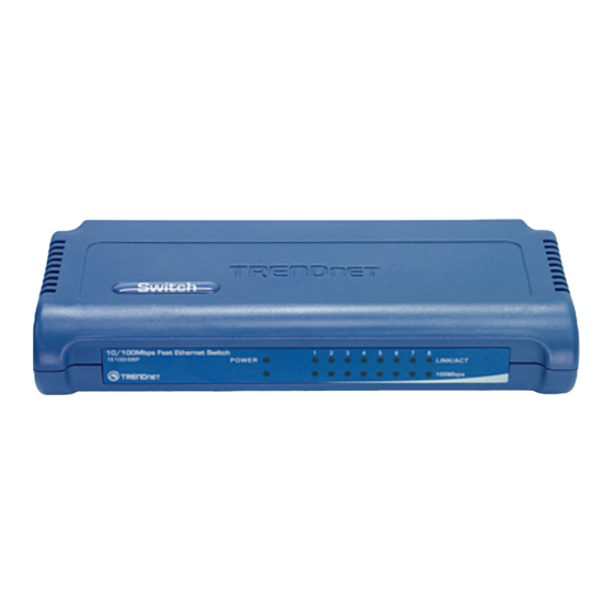
DENTIFYING This section identifies all the major external components of the switch. Both the front and rear panels are shown followed by a description of each panel feature. The indicator panel is described in detail in the next chapter. Front Panel The figure below shows the front panels of the switch. -
Page 12: Rear Panel
AC/DC power adapter. Check the technical specification section for information about the DC power input voltage. Since the switch does not include a power on/off switch, plugging its power adapter into a power outlet will immediately power on the Switch. -
Page 13: Led Indicators
LED Indicators When you power on the Switch, all LEDs will be ON for about 1 second and then go OFF, only the Power LED will stay lit. For 5-port switch Power This indicator lights green when the hub is receiving power. It is off for no power. - Page 14 For 8-port switch Power Indicator (PWR) This indicator lights green when the hub is receiving power. It is off for no power. LINK / ACT (Link/Activity) (green) This indicator lights green when the port is connected to a Fast Ethernet or Ethernet device. The indicator blinks green when there is activity on the port.
-
Page 15: Connecting The Switch
The connection is accomplished from the any RJ-45 port on the hub to any RJ-45 port on the Switch. After connecting the hub to the Switch, the Switch’s Port LED indicator will light according to the hub’s connection speed. If the port LED indicator does not light after making a proper connection, check the hub, the cable, and the Switch’s functionality. -
Page 16: Switch To Switch ( Other Devices )
Switch to switch (or other Ethernet devices) You can connect a switch or other Ethernet devices (10BASE- T or 100BASE-TX) to this Switch via a two-pair Category 3, 4, 5 UTP/STP cable (use Category 5 for 100Mbps connection). The connection is accomplished from the any RJ -45 port on the device to any RJ-45 port on the Switch. -
Page 17: Pin Specification
RJ-45 P The following diagram and table show the standard RJ-45 receptacle/connector and its pin assignments. RJ-45 Connector pin assignment Contact The standard cable, RJ-45 pin assignment The standard RJ-45 receptacle/connector PECIFICATION Media Direct Interface Signal TX + (transmit) TX - (transmit) Rx + (receive) Rx - (receive) Not used... -
Page 18: Technical Specifications
5 or 8 x 10/100Mbps auto-negotiation, auto-MDI ports Physical and Environmental DC inputs DC 7.5V, 1A Power TE100-S5P: 7.5W (Max.) Consumption TE100-S8P: 2W (Max.) Temperature Operating: 0 ~ 50 C, Storage: -10 ~ 70 C Humidity Operating: 10% ~ 90%, Storage: 5% ~ 90% PECIFICATIONS General... - Page 19 Dimensions TE100-S5P: 116 x 70 x 25 mm (W x H x D) Te100-S8P: 171 x 98 x 29 mm (W x H x D) EMI: FCC Class B, CE Mark B, VCCI-B Transmission Store-and-forward Method: Packet 10Mbps Ethernet: 14,880pps (packet per second)
Need help?
Do you have a question about the TE100-S8P and is the answer not in the manual?
Questions and answers