Table of Contents
Advertisement
0
dB
HI
+10
0
-10kHz
z-1kHz
dB
-12
+12
UENCY
MAX
E Q
M
DIRECT
OUT 1
INSERT
TUBE STAGE
JACK
TIP: SEND
RING: RETURN
SLEEVE: GROUND
INSERT
LIMITING
MIN
MAX
LIMIT
RELEASE
c o r e
c o r e
c o r e
REFERENCE CHANNEL STRIP
SLOW
FAST
LIMITER
OWNER'S MANUAL
MAIN
OUTPUT
OUT 2
GAIN
EQ
FET
BRICKWALL
LIMITER
DIRECT OUTPUT (1)
0
dB
-6
+4
OUTPUT
GAIN
REFERENCE CHANNEL STRIP
LINE INPUT
R
O/P 1
c o r e
MIC INPUT
O/P 2
GR
XLR PINOUT
PIN1: SHIELD/GROUND
PIN2: HOT/POSITIVE PHA
PIN3: LOW/NEGATIVE PH
Advertisement
Table of Contents

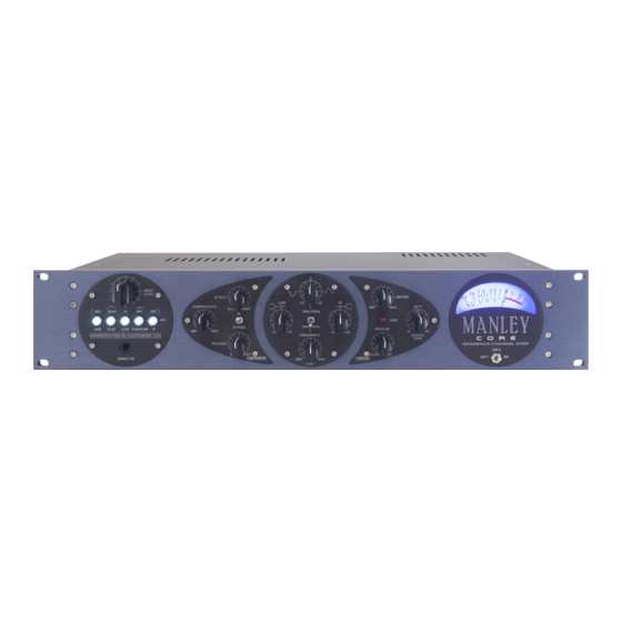
Summary of Contents for Manley CORE
- Page 1 LIMITING -10kHz LIMIT z-1kHz RELEASE c o r e c o r e c o r e OUTPUT UENCY GAIN REFERENCE CHANNEL STRIP O/P 2 SLOW FAST O/P 1 LIMITER OWNER’S MANUAL DIRECT MAIN OUTPUT OUT 2 OUT 1 GAIN c o r e BRICKWALL INSERT...
-
Page 2: Table Of Contents
Manual Conventions Important Safety Instructions Getting Started Front Panel Input Section Optical Compressor Equalizer Limiter VU Meter Rear Panel Rear Panel Connections Operational Notes Questions Copyright Notice Servicing Core Calibration Procedure 11-12 Curves & Specifications Recall Sheet c o r e... -
Page 3: I) Introduction
ELOP Compressor, an EQ section and a fast FET Brickwall Limiter. Musical. Flexible. Forgiving. These three concepts were my main goals in designing the CORE channel strip. To give the musician tools he or she really needs, without needless complication. Why is this important? Because recording has become more complicated than ever! Computers, plug-ins, and software can easily distract from creating your music. -
Page 4: Important Safety Instructions
2. Object and Liquid Entry – Care should be taken so that objects do not fall, and liquids are not spilled, into the enclosure through the openings. 3. Heat & Ventilation – When installing The CORE in a rack or any other location, be sure there is adequate ventilation. Improper ventilation will cause overheating, and can damage the unit. -
Page 5: Front Panel
Final Output Direct Input As the signal flow in the CORE is from right to left, we'll describe the functions in that order as well: 4. Input Section The INPUT LEVEL control is an input attenuator. It functions like a variable pad. -
Page 6: Optical Compressor
® Compressor ELOP ® ELOP Compressor utilizes our famous circuit topology as ® ® , and is also similar to the found in the VOXBOX ELOP and SLAM limiters. The COMPRESSION (Threshold) control determines at what level the compressor begins to act. Clockwise rotation makes the compressor reduce the signal. -
Page 7: Limiter
O/P 1- shows the audio level of the DIRECT OUTPUT of the preamplifier and compressor section. O/P 2 - shows the MAIN OUTPUT audio level of the CORE. GR - indicates the amount of COMPRESSOR gain reduction in decibels. This position stays at “0 VU” when there is no gain reduction and moves to the left to show the amount of compression. -
Page 8: Rear Panel
ELECTRIC SHOCK. DO NOT OPEN. REFER SERVICING TO QUALIFIED PERSONNEL ONLY. INSTRUMENT ® ATTENUATOR FILTER STAGE COMPRESSOR LINE IN LINE STAGE MANLEY LABORATORIES INC. MAIN OUTPUT (2) 13880 91710 MAGNOLIA AVE. CHINO, CA PHONE +1 (909) 627-4256 service@manleylabs.com www.manley.com Serial Number HANDCRAFTED IN USA... -
Page 9: Digital To Analog Converter
Diagram 7 INPUT (FRONT PANEL) MAIN DIRECT OUTPUT OUT 2 OUT 1 GAIN c o r e BRICKWALL INSERT TUBE STAGE LIMITER JACK REFERENCE CHANNEL STRIP LINE INPUT XLR PINOUT DIRECT OUTPUT (1) MIC INPUT TIP: SEND PIN1: SHIELD/GROUND RING: RETURN PIN2: HOT/POSITIVE PHASE SLEEVE: GROUND PIN3: LOW/NEGATIVE PHASE... -
Page 10: Rear Panel Connections
NO connection on XLR pin 3. This is important in order to prevent damage to the CORE, as well as distortion to the signal. DO NOT GROUND PINS 2 OR 3 on the MAIN O/P 2. -
Page 11: Questions
No part of this document may be produced, in any form, without prior written permission of Manley Laboratories, Inc. ® ® ® ® CORE , ELOP , VOXBOX , MANLEY and the Manley Laboratories, Inc. logo are trademarks of Manley Laboratories, Inc. c o r e... -
Page 12: Servicing
Diagram 9 TEST POINT LOCATION 15. Core Calibration Procedure The CORE requires calibration for 3 sections of its circuitry: VU METER- Adjust: +4dBu (1.228 Volts RMS) = “0” VU, Meter “GR” zero set ® ii) ELOP COMPRESSOR - Adjust: Gain Reduction (Audio & Meter GR) iii) FET PEAK LIMITER - Adjust: reference voltage &... - Page 13 Note-1: if you do not have enough output level coming from your oscillator, then increase the signal level coming into the CORE by adjusting the INPUT LEVEL ATTENUATOR control. Bring up the input level attenuator until you have a reading of +21dBu at the output XLR “OP2”.
-
Page 14: Curves & Specifications
16. Curves & Specifications ALL-TUBE preamplifier audio path using 1 x 12AX7WA for gain and 1 x 6922 White Follower Ÿ Balanced Transformer Coupled XLR Microphone Input Impedance: 1250 Ohms Ÿ EQ SHELF Balanced XLR Line Input Impedance: 10 kOhms Ÿ... -
Page 15: Recall Sheet
17. Recall Sheet c o r e... - Page 16 ELECTRIC SHOCK, DO NOT EXPOSE THIS UNIT TO RAIN OR MOISTURE CAUTION : RISK OF OPERATIONAL BLOCK DIAGRAM PHASE ELECTRIC SHOCK. DO NOT OPEN. REFER SERVICING TO QUALIFIED PERSONNEL ONLY. Designed & Handcrafted in USA INSTRUMENT ® Manley Laboratories, Inc. ATTENUATOR FILTER STAGE 13880 Magnolia Avenue COMPRESSOR LINE IN...


Need help?
Do you have a question about the CORE and is the answer not in the manual?
Questions and answers