Table of Contents
Advertisement
Quick Links
GB
Sound speed controller SFR-1
Operating manual
Sound Speed
Controller
SFR-1
V1.10
BEIER-Electronic
Winterbacher Str. 52/4, 73614 Schorndorf - Weiler
Telefon 07181/46232, Telefax 07181/45732
eMail: modellbau@beier-electronic.de
Internet:
http://www.beier-electronic.de/modellbau
06.02.2019
BEIER-Electronic
1
Advertisement
Table of Contents

Related Manuals for BEIER-Electronic SFR-1


Summary of Contents for BEIER-Electronic SFR-1
- Page 1 Sound speed controller SFR-1 Operating manual Sound Speed Controller SFR-1 V1.10 BEIER-Electronic Winterbacher Str. 52/4, 73614 Schorndorf - Weiler Telefon 07181/46232, Telefax 07181/45732 eMail: modellbau@beier-electronic.de Internet: http://www.beier-electronic.de/modellbau 06.02.2019 BEIER-Electronic...
-
Page 2: Table Of Contents
Digital switches at sum signal SUMD3 ..............35 Switching outputs ..................... 35 Output sequences ....................42 Servo outputs ......................43 Function sequences ....................44 Voltage monitoring ....................44 Current monitoring ....................45 LEDs on SFR-1 ......................46 Kraftwerk EasyBus lighting boards ................47 BEIER-Electronic 06.02.2019... - Page 3 Sound speed controller SFR-1 PC software „SFR-1 Sound-Teacher“ ..............48 Using software „SFR-1 Sound-Teacher“ ..............50 Saving sounds and configurations on SD card ............85 Transferring configurations with data cable K-USB-2 ..........86 Adjustments of driving sound with the driving sound diagram ........87 Sound simulation ......................
-
Page 4: Introduction
SM-IR-16-2, to forward light signals to a trailer. The SFR-1 is suitable for all types of RC standard transmitter. With the various setting options the SFR-1 can be easily adjusted to nearly all model requirements and driving behaviours. -
Page 5: Safety Notes
YouTube tutorials If you have questions about basic functions of the sound module SFR-1, please watch our YouTube video tutorials with English subtitles. In these videos we explain for example how to connect the sound module and how to program and control different functions. -
Page 6: Technische Daten
Sound speed controller SFR-1 Technische Daten Supply Voltage (U 6 – 18 V DC Power consumption: Bias current: approx. 1 mA Standby current (sound, motor and outputs off): approx. 80 mA Motor current: Max. 30 A continuous current, 60 A short-term current (1 minute) BEC voltage: approx. - Page 7 Sound speed controller SFR-1 • Short circuit protection at motor output stage Protection features: • Short circuit protection at switching outputs • Short circuit protection at BEC • Temperature monitoring • Battery voltage monitoring • Protection while switching on power supply •...
-
Page 8: Pin Assignment
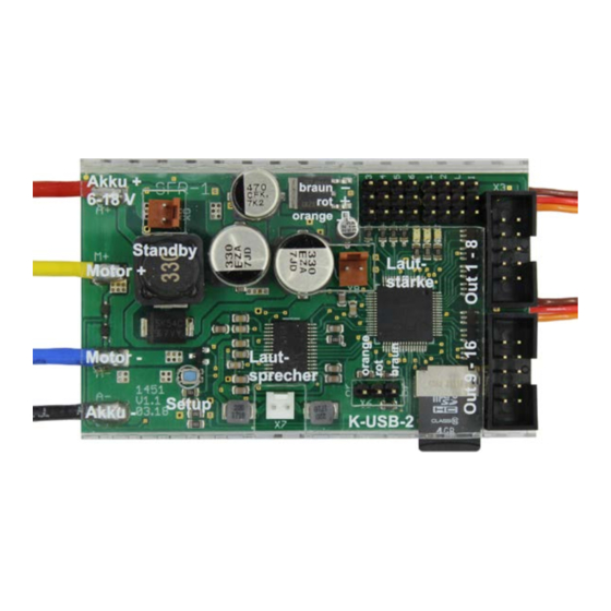
Sound speed controller SFR-1 Pin assignment Connections at SFR-1: X1/A+ Battery + / Akku + (6 – 18 V) X1/A- Battery - / Akku - X1/M+ Motor + X1/M- Motor - X2/1 Proportional input #1 (throttel channel) X2/2 Proportional input #2 (steering channel) -
Page 9: Wiring Diagram
Sound speed controller SFR-1 Wiring diagram Prop #1: throttle 06.02.2019 BEIER-Electronic... -
Page 10: Installation
Always switch off power before connecting the module! Connection of supply voltage (battery) The SFR-1 is suitable for 6 – 18 V DC. Choose a suitable battery for your motor. In order to connect the power supply the red cable is connected to the positive pole of the battery and the black cable to the negative pole of the battery. - Page 11 Sound speed controller SFR-1 If you want to disconnect the supply voltage of the SFR-1 from the battery, always disconnect the positive lead of the battery first (or plus and minus at the same time)! Never disconnect the negative lead first (or only)!
- Page 12 You do not have to connect channel #1 of the receiver with channel #1 of the SFR-1. If the joystick (to accelerate your model) is for example at channel #3 of the receiver, you have to connect channel #3 of the receiver with channel #1 of the SFR-1.
- Page 13 Of course other cables/plugs with a cross section of 0,14 mm² - 0,5 mm² can be connected as well. The SFR-1 is always switching the negative pole to each output and thus to the connected load. The positive pole is always connected permanently to the load (see wiring diagram).
- Page 14 However, if the model is not for several days, the battery should be disconnected completely. If no switch is connected to X9 or the switch is not closed, the SFR-1 will operate normally.
- Page 15 Sound speed controller SFR-1 General remarks for wiring Always use cables with a core diameter of at least 1,5 mm² for connecting the power supply and the motor. For all other connections, such as lights you can use smaller cables such as 0.25 mm².
-
Page 16: Setup (Teaching Function)
The SFR-1 is delivered with following standard setting: neutral position (1,5 ms), minimal position (1,0 ms) and maximal position (2,0 ms). We recommend to „teach“ the SFR-1 with the radio at least once. The motor is not used during the setup. -
Page 17: Loudspeaker
Sound speed controller SFR-1 Loudspeaker You can connect every loudspeaker to the SFR-1, which has an impedance of at least 4 Ω and is designed for the respective maximal power. We recommend using full range loudspeakers with 4 or 8 Ω. Higher impedances are also possible, but the volume decreases with higher impedances. -
Page 18: Volume Control
“Volume -“, must be configured in the Sound-Teacher e.g. to a proportional channel or to a nautic/multiswitch. General notes to volume Please note that the sound files you transfer to the SFR-1 should have an optimal modulation/volume. Common mistakes are far too quiet recordings that can not be played properly. -
Page 19: Sounds
Sound speed controller SFR-1 Sounds All sounds are stored in the SFR-1 with our software SFR-1 Sound-Teacher, in so called „slots". You don’t have to use every slot. If you don’t want e.g. any starting-noise, just keep the starting-noise slot free. -
Page 20: Engine Sound
Sound speed controller SFR-1 Engine sound The engine sound consists of several single<A[single|individual]> noises. Normally there is an engine start noise, an idling noise, a driving noise and an engine stop noise. This module also offers the possibility to imitate up to five different driving... - Page 21 (e.g. slow, normal and fast). Please keep in mind; the “gears” are just generated by the SFR-1 and not through a mechanic gearshift. Yet it is not possible to activate the different sounds through an engine control or a real gearshift.
-
Page 22: Turning On/Off Engine Sound
Turning on/off engine sound The SFR-1 can only play an engine sound, if it has been switched on before. There are different ways to switch on the engine sound: Using a proportional channel (X2/3 - X2/6) to switch on engine sound: If you have a joystick/slider/switch/rotary switch left, you can use it to switch the engine sound on or off. -
Page 23: Engine Sound 2
Sound speed controller SFR-1 Using nautic-mode on proportional channel #3 (X2/3) and #4 (X2/4) to switch on engine sound: If you have a nautic swich unit installed in your receiver, you can assign the function “engine sound on/off" to a nautic switch (Configuration Nautic/multiswitch) to turn the engine sound on or off with the selected switch (see page 33). -
Page 24: Functions Of Sfr-1
2. These functions continue to be controlled through the throttle channel at the normal engine sound. Functions of SFR-1 Additionally to the driving sound, the SFR-1 offers more features, which can be controlled by the remote control or the switching-inputs. Overview of all the functions: •... - Page 25 Sound speed controller SFR-1 • Ship: Constrained by draught • Ship: Towing • Ship: Assisting • Ship: Fishing • Smoke generator • Change of direction Speed controller • Throttle curve 2 • Load regulation on / off • Cruise control on / off •...
-
Page 26: Additional Sounds 1 - 30
Sound speed controller SFR-1 Additional sounds 1 - 30 In addition to the engine sound, the SFR-1 can play up to 30 additional sounds. Typical sounds are e.g. horns, hydraulic and pneumatic noises, warning horns, shooting noises, Songs, radio calls, and so on. There are nearly no limits set to your imaginations. - Page 27 Sound speed controller SFR-1 Loop / immed. stop When the sound is started, it is played again and again from start to finish in an endless loop. To switch the sound off it must be virtually “started” again. The sound then stops immediately.
-
Page 28: Random Sounds
Sound speed controller SFR-1 Random sounds Up to eight random sounds can be played with the SFR-1. The frequency of the sound play-back is determined by a random generator. The time spans (min/max) can programmed by 1 – 250s for every sound separately. In the same way the conditions (idling/drive - engine sound on/off) the sound should be played can be programmed for each of the 8 random sounds. - Page 29 Sound speed controller SFR-1 After track 30 the internal counter will jump back to track 1. By the way, the sound module always remembers the current track number. The next time the power supply is switched on, this track number “will be loaded“ again. If any changes are made to the SD card via the Sound-Teacher, the track counter will be reset to track number one.
-
Page 30: Functional Assignment At Proportional Channels #1 - #6
Sound speed controller SFR-1 Functional assignment at proportional channels #1 - #6 The proportional channel #1 is only responsible for the speed recognition. The remaining 5 channels can be configured in the Sound-Teacher with different functions. (100) (2,0ms) To occupy the proportional... - Page 31 Sound speed controller SFR-1 If a function is defined as static, it will be If a function is defined as memory and switched on as long as the joy-stick is in you move the joy-stick for the specified the corresponding area. If you leave the...
-
Page 32: Stick Simulation Via Keys Or Switches
Sound speed controller SFR-1 Stick simulation via keys or switches To use the functions of the proportional channels #2 - #6 conveniently, you can simulate the different potentiometer positions of a stick, through a simple keystroke. If you press the key... -
Page 33: Nautic Mode / Multiswitch Mode
With correctly received data from the switch module, the blue LED on the SFR-1 always flashes at regular intervals. -
Page 34: One-Channel Multi-Function Selection (Ekmfa)
Using the Sound-Teacher all 16 channels of the sum signal can be assigned to one of the 16 propotional channels of the SFR-1. It is important to use Prop #1 at the SFR-1 for the throttle channel of the transmitter. BEIER-Electronic... -
Page 35: Digital Switches At Sum Signal Sumd3
16 outputs by using the Sound- Teacher (see page 69). The SFR-1 is always switching the negative pole to each output and thus to the connected load (e.g. LED, lamp, relay). The loads plus pole is connected directly to the supply voltage, or to the black and white cables of the output blocks (collected plus pole). - Page 36 Sound speed controller SFR-1 • High beam headlight • Front fog light • Rear fog light • Brake light • Reversing light • Indicator left • Indicator right • Bending light left • Bending light right • Combined headlight • Combined rear light •...
- Page 37 Sound speed controller SFR-1 Output “Flashing“ on An output with this setup can be switched on using a sound, a proportional channel, a nautic switch or the EKMFA-mode. The output flashes as long as a sound is played, with which the output is activated in the Sound-Teacher or the output is switched on with one of the free allocable functions.
- Page 38 Sound speed controller SFR-1 “Parking light“, “Low beam headlight“, “High beam headlight“, “Front fog light“ and “Rear fog light“ outputs The outputs for these lights are switched on as soon as the corresponding function is switched on. The function can be switched on using a proportional channel, a nautic switch or the EKMFA-mode.
- Page 39 Sound speed controller SFR-1 Output „Combined headlight“ Using the combined headlight, “parking light“, “low beam headlight“ and “high beam headlight“ can be switched using just one output. The Intensity for each of the 3 lights can be adjusted seperately: The intensity of the parking light is entered under “intensity“(e.g. 10%).
- Page 40 Sound speed controller SFR-1 Output „Stationary/Motion“ With this function the output is always active, regardless of whether the model is moving or not. The value “Intensity” defines the light intensity during standing. “Option 1” defines the intensity when the model is in motion (0-100%). The change between both light intensities is executed smoothly.
- Page 41 Sound speed controller SFR-1 Outputs for ships With these outputs the lights of ships can be authentically simulated. The lights are controlled using this logic-table: Function At anchor Aground In operation Restricted in ability to ...
-
Page 42: Output Sequences
Sound speed controller SFR-1 switched to the condition "in operation". If the ship is stopped (throttle stick in neutral), the condition "in operation" will be switched off after an adjustable time and usually it will be switched over to the condition "at anchor". However, if in this moment there is still another condition active, like e.g. -
Page 43: Servo Outputs
The servo outputs deliver usual pulses from 1,000 - 2,000ms, so you can connect standard servos or speed-controllers. The power supply for these servo outputs is the integrated BEC of the SFR-1. There are two different ways to control the servo outputs: 1. -
Page 44: Function Sequences
Sound speed controller SFR-1 Function sequences All functions that can be triggered with the sound module (see page 24) can be compiled to a special function sequence with defined order and time for each step. More information can be found in this manual starting on page 83. -
Page 45: Current Monitoring
Sound speed controller SFR-1 11,1 V (3 cells) 9,9 V 9,6 V 14,8 V (4 cells) 13,2 V 12,8 V Lithium – iron 6,6 V (2 cells) 5,0 V 4,5 V phosphate (LiFe) 9,9 V (3 cells) 7,5 V 6,6 V... -
Page 46: Leds On Sfr-1
Sound speed controller SFR-1 LEDs on SFR-1 There are three LEDs on the sound module to show different conditions. Green LED The green LED allways lights up while the supply voltage is connected to X1/A+ and X1/A-. Red and blue LED These two LEDs show different conditions and errors. -
Page 47: Kraftwerk Easybus Lighting Boards
Please note: The EasyBus lighting boards or the EasyBus adapter have to be connected at X5/1 (Servo 1) of the SFR-1. Therefore, the servo output X5/1 can not be used to connect a servo anymore! The 16 switching outputs of the SFR-1 can nevertheless be used for further lighting. -
Page 48: Pc Software „Sfr-1 Sound-Teacher
Sound speed controller SFR-1 PC software „SFR-1 Sound-Teacher“ With our software „SFR-1 Sound-Teacher“ the module can be configured and sound files can be tranfered to the SD-card. System requirements • Windows compatible PC • Windows 2000, NT, XP, Vista, Windows 7, Windows 8 or Windows 10 •... - Page 49 3. Chose the SD card in the menu “SD card“. 4. Klick in the menu “File“on “Open project“. 5. Now select the desired sound project (.sfr file) e.g. from the “SFR-1 Sounds” folder on the DVD-ROM, and click on the button “Open”.
-
Page 50: Using Software „Sfr-1 Sound-Teacher
Open Sound-Center Opens the BEIER-Electronic Sound- Center, a sound data base from our cutomers Diagnosis via SD card Shows saved diagnostic data of the SFR-1 stored on the SD card SD card Formating SD card Formates (erases) the SD card... - Page 51 Sound speed controller SFR-1 Configuring sounds A lot of different sounds can be saved in the sound slots of the SFR-1. The sounds are divided into five different ranges: • Engine sound • Engine sound 2 • Additional sounds • Random sounds •...
- Page 52 Therefore the Sound-Teacher asks, when you are saving a project, to copy all files to the project directory. Configuring the sound module Click on the “configuration“ tab in order to carry out adjustments to the SFR-1. The settings are divided up into different ranges: • General •...
- Page 53 If the diagnosis function is activated, the sound playback may be faulty. If EasyBus lighting boards from Kraftwerk are to be controlled by the SFR-1, this must be activated here. Further information, see page 47. Volume You can also configure the basic volume (10-100%) of the module here.
- Page 54 Sound speed controller SFR-1 To obtain a more realistic driving sound a speed-dependent increase of volume can be activated with "Increase volume at topspeed". The volume of the driving sounds will be louder, the faster the model drives. In standing position the volume is automatically by this percentage less! Therefore, we recommend selecting a low value at this setting.
- Page 55 The cruise control can be deactivated while driving backwards. Brake function: With the brake function the vehicle can be slowed down by the SFR-1. The stronger the throttle stick is pressed down, the stronger the vehicle brakes. To drive backwards the driving direction must be changes with function „Change of direction“.
- Page 56 Sound speed controller SFR-1 Driving modes There are 4 driving modes, combining the functions cruise control and braking. Depending on the driving mode the throttle channel is used differently: No cruise No cruise with cruise control with cruise control control...
- Page 57 100 % make the steering angle larger. It is important to check first, if the steering servo is suitable for large angles. When driving between stationary and full throttle the SFR-1 calculates the corresponding steering angle within the defined max/min values.
- Page 58 Sound speed controller SFR-1 Hardness of handbrake If the function handbrake is activated with DIP switch 4 the hardness of braking can be set here. The handbrake can be active only while parking/standing. Without this option, the handbrake hits as soon as the throttle is in neutral position and the vehicle is still rolling.
- Page 59 Sound speed controller SFR-1 Configuration – Engine Sound – Engine Sound Engine sound options Thresholds for slow down and speed up: These thresholds set how strong the speed must be changed so that the normal driving sound is changed to deceleration or acceleration.
- Page 60 Sound speed controller SFR-1 off in order to play the coldstart sound instead of the warmstart sound after a new start. Speed change when triggering function “Engine sound rpm change”: Here you can setup the change of the rpm for idle or driving sound between a range of -50% and +50%.
- Page 61 Sound speed controller SFR-1 Configuration - Engine Sound - Engine Sound 2 Different parameters for engine sound 2 can be configured in this section. Speed via proportional channels: Proportional channels #1 - #6 can be used as source/recognition for speed.
- Page 62 Sound speed controller SFR-1 Configuration - Random sounds Random sounds If you want to play random sounds (see page 28), you can set the time in which interval a random sounds should be triggered. The time ranges between 1 and 999 seconds.
- Page 63 If sum signals should be used, they must be activated here. The sum signal channel of the receiver is connected to proportional channel #6 (X2/6) of the SFR-1. Each sum signal channel can be assignet to a proportional channel in the Sound-Teacher (see page 34).
- Page 64 Assignments and thresholds for proportional channel #2 - #6 For proportional channel #2 - #6, the ranges A, B, C and D can be assigned to various functions of the SFR-1. The left picture shows five ranges of a channel. You can define the thresholds for each range manually (see page 30) by moving the blue sliders up and down.
- Page 65 Configuration - Nautic/Multiswitch If you want to use the nautic mode 1 or 2, you will first have to activate it here and connect the SFR-1 prop. channel #3 (X2/3) or #4(X2/4) to the receiver channel. Switch assignment Every switch position can be assigned to a function (see page 24).
- Page 66 Sound speed controller SFR-1 Configuration - EKMFA If you want to use EMKFA mode, you have to activate it first. The used functions for EKMFA mode (see page Fehler! Textmarke nicht definiert.) can be configured here. Of course, you don’t have to assign every position (2 x 15 positions).
- Page 67 Kraftwerk. The control pad channel is connected from the receiver output to channel # 3 (X2 / 3) or channel # 4 (X2 / 4) of the SFR-1. The control pad can trigger up to 44 functions: •...
- Page 68 Sound speed controller SFR-1 Teach-in the control pad: Before first use, the SFR-1 must be taught-in on the control pad and the transmitter. This works as follows: 1. Connect throttle channel, steering channel and all other proportional channels you want to use to your receiver.
- Page 69 Configuration - Outputs The colored small boxes next to each output indicate the color of the flat ribbon cable that is connected to each output at the SFR-1. Output type You can assign 16 switching-outputs to various output types/characteristics (see page 35).
- Page 70 Sound speed controller SFR-1 Configuration - Outputs - Output options If the function “Light flickering when starting“ is activated, all 16 outputs will flicker while the starting noise (coldstart or warmstart) is played. The light bulb effect can be set in 3 levels: Light, medium and strong.
- Page 71 Sound speed controller SFR-1 Indicator lights: The indicator can also (e.g. like in a real car) be switched off with the steering channel prop. #2. The lights flash until the steering channel returns to neutral position. The indicator light threshold determines how strong the vehicle must turn until the indicator light is activated.
- Page 72 Sound speed controller SFR-1 The ship light functions can be configured to detect automatically the condition of "in operation" or "at anchor" using the throttle channel #1. The condition "in operation" is automatically switched off, if the throttle channel is in neutral for a defined time. After the time has expired (1-255s), it will be switched for example from "in operation"...
- Page 73 Sound speed controller SFR-1 After turning on the sound module the light switch is automatically in step 0. With the reset button all settings are reset to standard. 06.02.2019 BEIER-Electronic...
- Page 74 Sound speed controller SFR-1 Configuration - Outputs -Sequences With the SFR-1 up to 16 outputs can be combined and activated in a defined sequence (duration and intensity). This can be parallel or in a row. In total 8 output sequences can be programmed, each with 36 steps.
- Page 75 Sound speed controller SFR-1 In each step you can set for each output the desired intensity. For this purpose, click with the mouse on the value that you want to change and select in the drop- down box the new value (0% - 100%).
- Page 76 Sound speed controller SFR-1 Output sequence 2: This example shows a simple fluorescent lighting simulation. Here is only one output used, however, the lamp switches not only on and off but it simulates the typical start of a fluorescent lamp.
- Page 77 Sound speed controller SFR-1 Configuration - Servo outputs - Servos 1 + 2 Here you can configure the two servo outputs of the SFR-1 (see page 43). If you want to use the servo outputs, you have to activate them here.
- Page 78 Sound speed controller SFR-1 If this option is not activated, the servo will not go back to home position during deactivation, but stays in the current position. This means, any position can be allocated to the servo. For this, the speed should be set relatively slow.
- Page 79 Sound speed controller SFR-1 For #1 and #2, e.g. a crane arm will turn slowly to the right and left and at positions #3 and #4 quickly. With "Speed" the acceleration (slow or fast) can be set from neutral (motor off) to the positions #1 - #4 (maximum rotation speed).
- Page 80 Sound speed controller SFR-1 Configuration - Servo outputs - Servos sequence 1 + 2 For both servo outputs you can program a time controlled flow sequences. A sequence may consist of up to 10 steps. For every step a servo position (1,000 - 2,000ms) must be assigned, that indicates the starting position of the servo.
- Page 81 Sound speed controller SFR-1 Sound at servo movement With this option the sound (additional sound) for the servo is always played as long as the servo moves. Sound when not in home position With this option, the sound will be played when the servo is not in home position (position of step 1).
- Page 82 Configuration - Servo outputs - SM-IR-16-2 servos 1 + 2 Both servo outputs of the light module SM-IR-16-2 can be configured similar to the servo outputs of the SFR-1. For details about the settings please read page 77 onwards. The only difference is that the SM-IR-16-2 has only 2 positions, #1 and #2.
- Page 83 Sound speed controller SFR-1 Configuration - Function sequences All functions of the SFR-1(see page 24) can be compiled to a timed sequence of up to 36 functions/steps. For each step a function can be selected and switched on or off. In Duration the time can be defined until the next step is activated.
- Page 84 Sound speed controller SFR-1 Project notes In project notes you have space for remarks about your project and settings. BEIER-Electronic 06.02.2019...
-
Page 85: Saving Sounds And Configurations On Sd Card
The sound module must be disconnected from the supply voltage before inserting or pulling out the SD card! 1. Pull out the SD card from the slot of the SFR-1. The card should be handled with care in order to prevent damage because the side with the golden contacts is very sensitive to scratches. -
Page 86: Transferring Configurations With Data Cable K-Usb-2
SFR-1 can not be found with data cable If the SFR-1 port can not be found with the data cable, check the port in the device manager. If there is a yellow warning sign a new hardware driver (Prolific) is required. -
Page 87: Adjustments Of Driving Sound With The Driving Sound Diagram
The range starts at 60% and goes up to 300 %. This percent refers to the play-back speed of the driving sounds (100 %) saved in the SFR-1 slots. A higher play-back speed (e.g. 150 %) equals a higher engine speed. - Page 88 Sound speed controller SFR-1 The thresholds can be adjusted with the red quadrates. As soon as the driving speed reaches the speed at the red line, a change of the driving sound takes place. Depending on the number speed steps/gears the same amount of red lines will appear.
-
Page 89: Sound Simulation
• Button 1 - 0 Additional sound 11 - 20 Testing functions with help of data cable K-USB-2 The function “Control SFR-1 functions with data cable” can be found under menu “Data cable”. With the help of the data cable K-USB-2, all functions can be controlled directly from the PC and not only via the remote control. -
Page 90: Diagnosis
Sound speed controller SFR-1 Diagnosis A diagnosis function is integrated in the SFR-1 to control different functions, values and features. There are two different types of diagnosis: 1. Diagnosis with datacable (live) 2. Diagnosis with SD card (recorded) The diagnosis window is divided into different areas: proportional channels, outputs, servo outputs, motor, nautic mode and others. - Page 91 The additional datacable K-USB-2 is needed for live-diagnosis. It is connected to X11. The brown cable points to the SD-card. A live-diagnosis using the data cable is generally only useful when the SFR-1 in the model is completely installed; wired and all necessary equipment is switched on (e.g.
- Page 92 Sound speed controller SFR-1 Record diagnosis with SD card You can also record diagnosis data from the SFR-1 to the SD card. This data can be displayed with the Sound-Teacher on the computer. Consider following points: • The must be enabled first in the Sound-Teacher.
-
Page 93: Firmware Update
The sound-Teacher writes the firmware file automatically while saving the project data onto SD card. A firmware update of the SFR-1 is always performed automatically when the Sound- Teacher version is different from the current version of the SFR-1 firmware. The firmware update will be started after the supply voltage is switched on and it takes 10 seconds. -
Page 94: Neue Sounds Am Pc Aufnehmen
Sound speed controller SFR-1 This part of the manual has not yet been translated into English… Neue Sounds am PC aufnehmen Auf der mitgelieferten DVD-ROM befinden sich einige Beispielsounds, mit denen Sie erste Versuche mit dem Soundfahrtregler tätigen können. Irgendwann wollen Sie sicher auch eigene Sounds auf Ihren Soundfahrtregler spielen. - Page 95 Sound speed controller SFR-1 Eine weitere Möglichkeit ist das Aufnehmen von eigenen Sounds. Als Quelle können beispielsweise ein Kassettenrekorder, ein MP3-Player, eine CD/DVD, Videokamera oder ein Mikrofon dienen. Auf der mitgelieferten DVD befindet sich eine Vollversion der Software „Audacity“. Zum Installieren der Software, starten Sie den „USM-Installer“, klicken auf „Audacity installieren“...
- Page 96 Sound speed controller SFR-1 einen Haken bei „Deaktivierte Geräte anzeigen“. Wird das verwendete Aufnahmegerät nicht angezeigt, kann eventuell ein neuer Treiber der Soundkarte Abhilfe schaffen. Stellen Sie nun wie unter Punkt 2 das Aufnahmegerät ein. c. Wenn Sie einen Sound aufnehmen möchten, der gerade auf Ihrem PC abgespielt wird (z.B.
-
Page 97: Sounddateien Konvertieren
6. In dem Fenster „Metadaten bearbeiten“ bitte nichts in die Felder eintragen, bzw. vorhandene Werte löschen. Ansonsten können die WAV-Dateien nicht über die Sound-Simulation im Sound-Teacher abgespielt werden! 7. Nun kann die neu erstellte Datei mit Audacity weiter bearbeitet, oder direkt mit unserer Software „SFR-1 Sound-Teacher“ geladen werden. 06.02.2019 BEIER-Electronic... -
Page 98: Sounds Am Pc Bearbeiten
Sound speed controller SFR-1 Sounds am PC bearbeiten Sound „verstärken“ Damit der Sound vom Soundfahrtregler auch laut genug abgespielt wird, muss der Sound auch dementsprechend ausgesteuert werden. In der Praxis hat sich gezeigt, dass ein gewisses Übersteuern die Soundqualität nicht gleich sehr verschlechtert, aber dafür die Lautstärke natürlich anhebt. - Page 99 Sound speed controller SFR-1 Sound „zurechtschneiden“ Zum Erstellen von brauchbaren Geräuschen, ist es oft notwendig einzelne Teile aus der Tonspur auszuschneiden, oder zu entfernen. Dazu benötigt man: 1. Das Auswahlwerkzeug zum Markieren 2. Das Zoomwerkzeug zum Vergrößern Vorgehensweise: 1. Suchen Sie sich aus der Tonspur, mit Hilfe des Zoomwerkzeugs einen Teil aus, den Sie verwenden möchten (Linksklick hineinzoomen, Rechtsklick...
- Page 100 Sound speed controller SFR-1 8. Wenn etwas gelöscht werden soll, nutzen Sie das Auswahlwerkzeug um den Teil zu markieren, der nicht mehr benötigt wird und klicken Sie im Menü „Bearbeiten“ auf „Löschen“. Einfaches Fahrgeräusch erstellen Ein „ganz einfaches“ Fahrgeräusch besteht aus einem Anlassgeräusch, der Schleife des Stand-/Fahrgeräusches und einem Abstellgeräusch.
- Page 101 Sound speed controller SFR-1 5. Im linken Fenster können Sie nun den Anfang der Markierung ablesen und im rechten Fenster das Ende. Notieren Sie sich das Ende. 6. Schneiden Sie sich dann ein passendes Anlassgeräusch aus. 7. Um das Anlassgeräusch zu verbessern, kann am Anfang ein „Einblenden“...
- Page 102 Sound speed controller SFR-1 12. Sie können sich die markierte Schleife als Endlosschleife anhören, indem Sie die Shift/Umschalttaste gedrückt halten und die grüne Wiedergabetaste drücken. 13. Die Schleife sollte ohne „Knacken“ und hörbare Unterschiede ineinander übergehen. Ist das nicht der Fall, so gibt es verschiedene „Tricks“ um die Schleife zu verbessern: a.
- Page 103 Sound speed controller SFR-1 h. Hören Sie sich die Schleife erneut an. i. Nutzen Sie das Zoomwerkzeug um „knackende Stellen“ zu finden und versuchen Sie mit Hilfe des Zeichenwerkzeugs diese zu verbessern. j. Solche Stellen können durch ruckartige Übergänge in der Tonspur...
- Page 104 Sound speed controller SFR-1 n. Schauen Sie sich auch den Anfang und das Ende der Schleife an und versuchen Sie mit dem Zeichenwerkzeug den Übergang zu verbessern. Bei dem linken Bild befindet sich das letzte Sample der Schleife im oberen Bereich. Wenn die Schleife jetzt wieder von vorne startet, folgt direkt ein Sample im unteren Bereich.
- Page 105 Sound speed controller SFR-1 17. Mit einem Klick auf „Projekt einpassen “ haben Sie eine bessere Übersicht. 18. Klicken Sie mit dem Auswahlwerkzeug an den Anfang des ersten Geräuschs und verwenden Sie die Wiedergabetaste um sich den Sound anzuhören. 19. Sie können auch die Schleife noch ein zweites Mal einfügen (mit „Datei“ und „Import“) und hinter die erste anhängen um sich den Übergang anzuhören.
- Page 106 Sound speed controller SFR-1 k. Falls nun wieder ein leichtes „Knacksen“ auftritt, beseitigt man dies am Besten erst nach dem Zusammenfügen der Tonspuren. l. Um Ihr neues Anlassgeräusch zusammenzuführen, entfernen Sie zunächst die Schleife und klicken Sie zweimal im Menü „Spuren“ auf „Spuren zusammenführen“...
- Page 107 Sound speed controller SFR-1 25. Erzeugen Sie zunächst ein „Ausblenden“ am Ende des Abstellgeräusches. Die zu wählende Länge ist abhängig vom Sound. Im Beispiel wären etwa 0,5s optimal. 26. Hören Sie sich dann den Übergang vom Standgeräusch zu Abstellgeräusch 27. Ist der Übergang schlecht, gibt es wieder Möglichkeiten diesen zu verbessern: a.
- Page 108 Sound speed controller SFR-1 f. Hören Sie sich nun das Geräusch an g. Wenn Sie zufrieden sind, können Sie nun Ihr fertiges Abstellgeräusch zusammenfügen. Dazu entfernen Sie zunächst das Standgeräusch. h. Klicken Sie dann zweimal im Menü „Spuren“ auf „Spuren zusammenführen“...
- Page 109 Sound speed controller SFR-1 Damit ist die Einführung in die Soundbearbeitung mit „Audacity“ beendet. Natürlich bietet das Programm noch mehr Möglichkeiten als die hier erklärten. Wenn Sie sich dafür interessieren, dann schauen Sie bitte in die Hilfe des Programms. 06.02.2019...
Need help?
Do you have a question about the SFR-1 and is the answer not in the manual?
Questions and answers