Table of Contents
Advertisement
Quick Links
GB
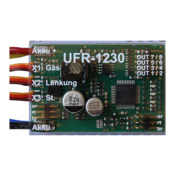
Speed Controller UFR-1230
Operating Manual
Speed Controller
UFR-1230
V1.12
BEIER-Electronic
Winterbacher Str. 52/4, 73614 Schorndorf - Weiler
Phone: 07181/46232, Telefax 07181/45732
eMail: modellbau@beier-electronic.de
Internet:
http://www.beier-electronic.de/modellbau
28.08.2018
BEIER-Electronic
1
Advertisement
Table of Contents

Related Manuals for BEIER-Electronic UFR-1230


Summary of Contents for BEIER-Electronic UFR-1230
- Page 1 Speed Controller UFR-1230 Operating Manual Speed Controller UFR-1230 V1.12 BEIER-Electronic Winterbacher Str. 52/4, 73614 Schorndorf - Weiler Phone: 07181/46232, Telefax 07181/45732 eMail: modellbau@beier-electronic.de Internet: http://www.beier-electronic.de/modellbau 28.08.2018 BEIER-Electronic...
-
Page 2: Table Of Contents
Current monitoring of outputs ................... 25 Monitoring of proportional inputs/failsafe ..............25 LEDs on UFR-1230 ....................26 Installation of software „UFR-1230 Drive-Teacher“ ..........27 How to use the software „UFR-1230 Drive-Teacher“ ..........28 Diagnosis ........................38 Firmware update ....................... 40 BEIER-Electronic... -
Page 3: Description
The speed controller is equipped with 8 switching outputs to connect LEDs and other lights directly. In addition the speed controller has an extra output for connecting the infrared diode from the light module SM-IR-16-2. The speed controller UFR-1230 has following characteristics: • Supply voltage 6 – 18 V •... -
Page 4: Safety Notes
Speed Controller UFR-1230 Additional functions are adjustable with the software "Drive-Teacher" and can be transferred with the data cable K-USB-2 (optional available): • Firmware update • Diagnosis • Invertion of channels • Deactivation of low voltage monitoring • Reduction of driving backwards speed to 50 % •... -
Page 5: Technical Data
Speed Controller UFR-1230 Technical data Supply voltage (U 6 – 18 V DC Power consumption: Stand-by current: approx. 40 mA Motor current: Max. 30 A continous current, 60 A short-term current (1 minute) BEC voltage: 5,2 V BEC current: Max. 3 A continous current,... -
Page 6: Pin Assignment
Speed Controller UFR-1230 Pin assignment black Battery+ orange orange Battery- Steering servo Sound module Battery + Battery - Switching outputs IR-Diode Data cable Connections at the speed controller: Battery red: battery +, black: battery - (Deans T female connector) Motor... -
Page 7: Wiring Diagram
Speed Controller UFR-1230 Wiring diagram Receiver Motor 28.08.2018 BEIER-Electronic... -
Page 8: Installation Of Speed Controller
Sound-Teacher, see page 29. Connection of receiver (X1, X2 and X3): 3 servo cables (X1 - X3) are soldered to the speed controller UFR-1230, for connecting the speed controller to the receiver. Servo cable... - Page 9 The speed controller has its own BEC supply voltage (only with X1) an additional receiver battery is not required. In case the BEC voltage of the UFR-1230 should not be used, the red cable from servo cable X1 and the red servo cable from X4/1 (sound module connection) must be disconnected.
- Page 10 Speed Controller UFR-1230 Assignment of flat ribbon cable: Output Flat ribbon cable brown orange yellow green blue purple grey Positive pole white Positive pole black When connecting the flat ribbon cable the black cable points up to the edge of the board.
- Page 11 • Read-out configurations of speed controller • Run diagnosis functions • Update of firmware The speed controller is not powered by the data cable. For using the data cable, the UFR-1230 must be supplied with power via the battery as normal. 28.08.2018 BEIER-Electronic...
-
Page 12: Connection To Sound Module Usm-Rc-2
• Additional outputs from the USM-RC-2 can be used for connecting lights, in case the 8 light outputs at the UFR-1230 are not enough. For this, only the types for the outputs must be selected in the Sound-Teacher. This works with... -
Page 13: Dip Switches
Speed Controller UFR-1230 For digital communication at least Sound-Teacher V1.50 is required. You also need to activate „Digital mode with UFR ESC“ in your Sound-Teacher (Configuration General General Module configuration). DIP switches Following functions can be activated and deactivated with the DIP switches:... -
Page 14: Cruise Control
Speed Controller UFR-1230 Cruise control With DIP switch 2 the cruise control can be activated (ON). With activated cruise control the throttle position controls not any longer the actual driving speed but the change in speed. In neutral position (throttle stick) the cruise control keeps the speed. -
Page 15: Selection Of Battery Type
Speed Controller UFR-1230 However, the EMF brake is not as effective as a mechanical brake. At a steep incline the vehicle may roll away despite the handbrake. Selection of battery type With a LiPo battery DIP switch 5 must be set ON. With all other types of batteries the switch is OFF. -
Page 16: Driving Mode
Speed Controller UFR-1230 Driving mode There are 4 driving modes, combining the functions cruise control and braking. Depending on the driving mode the throttle channel is used differently: No cruise control No cruise control with cruise control with cruise control... - Page 17 Speed Controller UFR-1230 • Rear fog light • Indicator left • Indicator right • Hazard light • Light switch + • Light switch - • Changing driving direction • Changing to throttle curve 2 • Load regulation on/off • Cruise control on/off •...
-
Page 18: Control Channel X3
Speed Controller UFR-1230 Control channel X3 With control channel X3 lights and other additional functions can be switched (see page 16). With the activated option „brake function“ (DIP switch 3) the driving direction must be changed with control channel X3. -
Page 19: Simulation Of A Control Stick With Switches
Speed Controller UFR-1230 Simulation of a control stick with switches In most cases the control sticks of a radio are occupied with other functions. Therefore you need a different option to control the functions of channel X3. With one free channel and two switches the different possitions of a poti / control stick can be simulated. -
Page 20: Nautic/Multiswitch
With the option „memory“ the function stays activated until the switch is pressed again. To use a nautic/multiswitch module the servo channel X3 of the UFR-1230 must be connected to the correct receiver output (corresponding to the used transmitter input). -
Page 21: Switching Outputs
Speed Controller UFR-1230 Switching outputs The UFR-1230 switching outputs can be used for connecting LEDs and other lights. The UFR-1230 is delivered with following output setting: Output Type Brake light Reversing light Parking light Low beam headlight Indicator left Indicator right... - Page 22 Speed Controller UFR-1230 Output „daytime running light“, „parking light“, „low beam headlight“, „high beam headlight“, „fog light“ and „rear fog light“ These outputs are activated, as soon as the light switch is in a step, where these lights are programmed. Alternatively, these outputs can also be switched by their "names"...
- Page 23 Output „Temperature controlled“ By using the temperature sensor on the board of the UFR-1230 you can control an additional fan, in order to cool the motor output stage. In configuration you can set the temeratures at which the fan should be activated and deactivated.
-
Page 24: Short Circuit Protection At Motor Output
Drive-Teacher, see page 34) • Flashing of red LED on the UFR-1230 Temperature monitoring The UFR-1230 contains an integrated sensor to monitor permanently the temperature. If the measured temperature exceeds 80 °C following actions are executed: • Reduction of driving speed to maximum 30 % •... -
Page 25: Low Voltage Monitoring
• Slowly flashing of reversing lights lights (you can change the output with your Drive-Teacher, see page 34) • Slowly flashing of the blue LED on the UFR-1230 When connecting a LiPo-, NiMh- or NiCd battery the speed controller recognizes the number of cells automatically. -
Page 26: Leds On Ufr-1230
Speed Controller UFR-1230 LEDs on UFR-1230 The speed controller has 3 LEDs to indicate the different states. State/Problem green LED red LED blue LED Ready for operation Throttle has not been in neutral position slow flashing fast Active teaching function... -
Page 27: Installation Of Software „Ufr-1230 Drive-Teacher
Speed Controller UFR-1230 Installation of software „UFR-1230 Drive-Teacher“ Additional options can be set at the speed controller with the Windows-based software „UFR-1230 Drive-Teacher“. A free download of the software is available on our website. At delivery the speed controller is ready for use. Therefore the software is only necessary when adjustments from the standard setting should be done. -
Page 28: How To Use The Software „Ufr-1230 Drive-Teacher
Speed Controller UFR-1230 How to use the software „UFR-1230 Drive-Teacher“ Menüs Create new project Creates a new project Open project Opens an existing project Save project Saves the current project Saves a copy of the current project with Save project as... - Page 29 Other Using digital communication all speed and light data are transferred from speed controller UFR-1230 to sound module USM-RC-2 with only one connection at X4/1, see page 12 for more information. In your Drive-Teacher the settings „Digital communication with sound module“ and in your Sound-Teacher „Digital mode with UFR ESC“...
- Page 30 100 % make the steering angle larger. It is important to check first, if the steering servo is suitable for large angles. When driving between stationary and full throttle the UFR-1230 calculates the corresponding steering angle within the set max/min values.
- Page 31 Speed Controller UFR-1230 useful whereas at high speed a smaller steering range enables a more sensitive steering. Hardness of handbrake If the function handbrake is activated with DIP switch 4 the hardness of braking can be set here. The handbrake can only be active while parking/standing. Without this option, the handbrake hits as soon as the throttle is in neutral position and the vehicle is still rolling.
- Page 32 Speed Controller UFR-1230 Configuration – Control channel X3 The picture shows the standard settings of the control channel X3. All available additional functions for control channel X3 are listed on page 16. Each of the 4 areas (A, B, C and D) can be set with 2 functions for short and long in position.
- Page 33 Speed Controller UFR-1230 Configuration - Nautic/Multiswitch In the standard setting the nautic mode is deactivated. Assignment of switches For each switch position a function can be set (see page 16) optional with the option „memory“. Type Select your transmitter type in this box.
- Page 34 Additional options are available for some outputs. More information can be found on page 21. Flash type The UFR-1230 offers 6 preset flash types (see page 24). The outputs can be assigned any flash types here. The flashers are all activated with the function "Flash", via the control channel X3, (or Nautic/Multiswitch).
- Page 35 Speed Controller UFR-1230 automatically on after heavy braking. The lights remain on, as long as they are switched off manually or the vehicle starts moving. With the option „Low beam with xenon HID turn-on effect“ the low beam lights switch on with the specific xenon effect (short flash with dimming).
- Page 36 Speed Controller UFR-1230 Light switch The light switch is individually programmable with up to 6 steps. For each step different lights can be activated. Using control channel X3 and the function „light switch +“ and „light switch -“ the steps can be changed.
- Page 37 Speed Controller UFR-1230 Configuration - SM-IR-16-2 All configurations of the SM-IR-16-2 can be set here. Home position After switching on the speed controller the servos are always in this position. Positions #1 - #2 With control channel X3 (additional functions) or with nautic/multiswitch modules the positions #1 and #2 can be controlled.
-
Page 38: Diagnosis
Speed Controller UFR-1230 Automatic return to home position, if no other position is selected With this option the servo always returns to its home position, if neither position #1 nor #2 is activated. This option is helpful in case a motor is connected to the servo output. - Page 39 Speed Controller UFR-1230 Servo outputs Current values of servo outputs X4 and X5. Motor A few values for the motor output stage are shown here. These values are only for internal checks. Various The values in this field are mostly for internal checks.
-
Page 40: Firmware Update
Speed Controller UFR-1230 Firmware update As soon as a new update is available you will get a notice from the Drive-Teacher. It is also possible to download the update manually. With every update of the software the firmware for the speed controller is updated as well.
Need help?
Do you have a question about the UFR-1230 and is the answer not in the manual?
Questions and answers