
Subscribe to Our Youtube Channel
Related Manuals for GMI D5097-107


Summary of Contents for GMI D5097-107
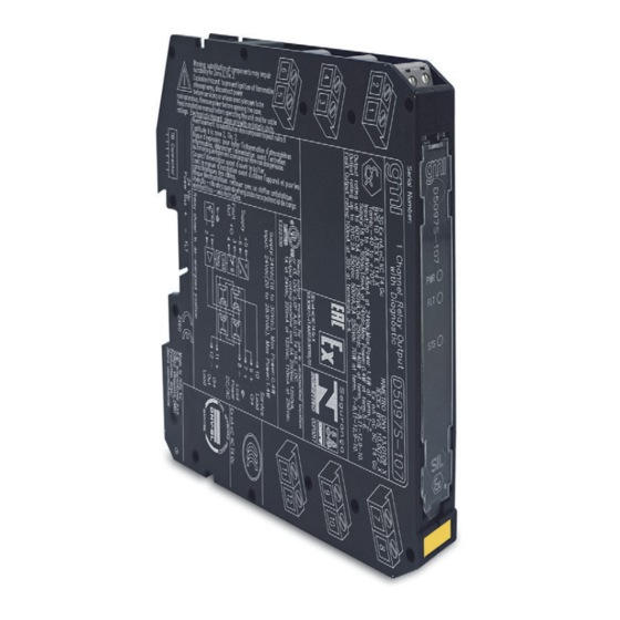
- Page 1 D5097S-107 INSTRUCTION MANUAL SIL3 Relay Low-V Module for 5 A NE/ND Loads with LFD DIN-Rail and Termination Board Model D5097S-107 D5097-107 - SIL 3 Relay Low-V Module for 5 A NE/ND Loads with LFD G.M. International ISM0463-4...
-
Page 2: Technical Data
F = available function NA = not available PF = available function with programmable thresholds (see smart relay modules for complete programmable diagnostics functions) D5097-107 - SIL 3 Relay Low-V Module for 5 A NE/ND Loads with LFD G.M. International ISM0463-4... -
Page 3: Ordering Information
(SIL 3) + Output NE Load or F&G/ND Load + Power Supply 24 Vdc (SIL 3) - Output NE Load or F&G/ND Load - Power Supply 24 Vdc G.M. International ISM0463-4 D5097-107 - SIL 3 Relay Low-V Module for 5 A NE/ND Loads with LFD... -
Page 4: Function Diagram
To prevent relay contacts from damaging, connect an external protection (fuse or similar), chosen according to the relay breaking capacity diagram. D5097-107 - SIL 3 Relay Low-V Module for 5 A NE/ND Loads with LFD G.M. International ISM0463-4... -
Page 5: Operation
Warning D5097-107 series are electrical apparatus installed on EN/IEC60715 TH 35 standard DIN-Rail located in Safe Area/Non Hazardous Locations or Zone 2, Group IIC T4 or Class I, Division 2, Group A, B, C, D, T4 Hazardous Area within the specified operating temperature limits Tamb - 40 to +70 °C.
Need help?
Do you have a question about the D5097-107 and is the answer not in the manual?
Questions and answers