Table of Contents
Advertisement
Quick Links
Advertisement
Table of Contents

Related Manuals for GMI D5091S


Summary of Contents for GMI D5091S
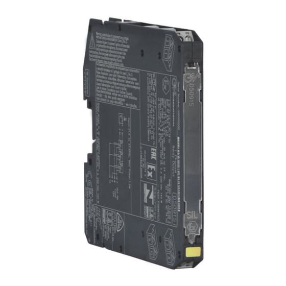
- Page 1 5 A SIL 3 Relay Output Module for ND Load with ND or NE Relay condition DIN-Rail and Termination Board, Model D5091S D5091 - 5 A SIL 3 Relay Output Module for ND Load with ND or NE Relay condition...
- Page 2 Characteristics General Description: The single channel Relay Output, D5091S is a relay module suitable for the switching of safety related circuits, up to SIL 3 level according to IEC 61508:2010 Ed.2 for high risk industries. It provides isolation between input and output contacts.
- Page 3 Ordering Information DIN-Rail accessories: Cover and fix MCHP196 Model: D5091S Front Panel and Features SIL 3 according to IEC 61508:2010 Ed. 2 for Tproof = 6 / 20 yrs (≤10% / >10 % of total SIF) for ND load with ND relay (terminals 7-8).
- Page 4 SAFE AREA, ZONE 2 GROUP IIC T4, NON HAZARDOUS LOCATIONS, CLASS I, DIVISION 2, GROUPS A, B, C, D T-Code T4, CLASS I, ZONE 2, GROUP IIC T4 MODEL D5091S (SIL3) SPDT Out ND Load 7-8 or 9-10 Relay contact shown in de-energized position.
- Page 5 Safety Function and Failure behavior: D5091S is considered to be operating in Low Demand mode, as a Type A module, having Hardware Fault Tolerance (HFT) = 0. In the 1st Functional Safety application, the normal state operation of relay module is de-energized, with ND (Normally De-Energized) loads.
- Page 6 Safety Function and Failure behavior: D5091S is considered to be operating in Low Demand mode, as a Type A module, having Hardware Fault Tolerance (HFT) = 0. In the 2nd Functional Safety application, the normal state operation of relay module is energized, with ND (Normally De-Energized) load.
- Page 7 The unit cannot be repaired by the end user and must be returned to the manufacturer or his authorized representative. Any unauthorized modification must be avoided. Operation D5091S relay module is suitable for the switching of safety related circuits, providing isolation between the input and output contacts. D5091S provides 1 SPDT contact for two different safety functions: 1) SIL 3 Safety Function for Normally De-Energized load (energized in fail safe state) is available at Terminal Blocks 7-8.
- Page 8 To prevent relay contacts from damaging, connect an external protection (fuse or similar), chosen according to the relay breaking capacity diagram from installation instructions. The enclosure provides, according to EN60529, an IP20 minimum degree of protection (or similar to NEMA Standard 250 type 1). The unit shall be installed in an area of no more than pollution degree 2 according to EN/IEC60664-1.
Need help?
Do you have a question about the D5091S and is the answer not in the manual?
Questions and answers