
Related Manuals for GMI D5094-104


Summary of Contents for GMI D5094-104
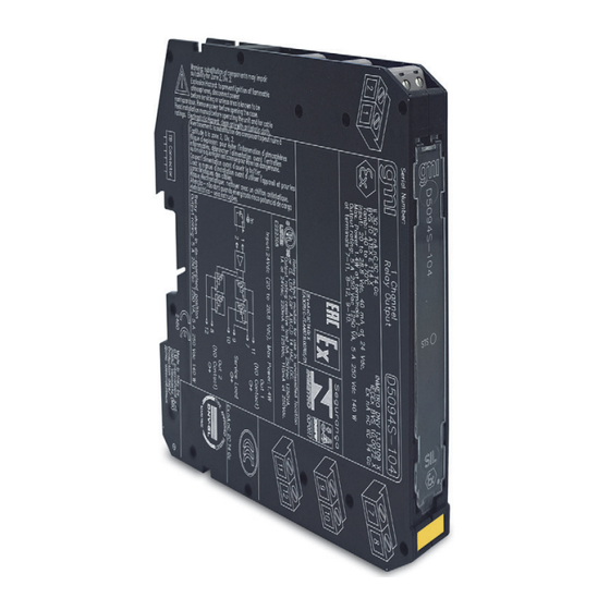
- Page 1 D5094S-104 INSTRUCTION MANUAL SIL3 Relay Low-Volt Module for 5 A NE/ND Loads DIN-Rail and Termination Board Model D5094S-104 D5094-104 - SIL 3 Relay Low-Volt Module for 5 A NE/ND Loads G.M. International ISM0460-4...
- Page 2 Location: installation in Safe Area/Non Hazardous Locations or Zone 2, Group IIC T4 or Class I, Division 2, Group A,B,C,D, T4. Protection class: IP 20. Dimensions: Width 12.5 mm, Depth 123 mm, Height 120 mm. D5094-104 - SIL 3 Relay Low-Volt Module for 5 A NE/ND Loads G.M. International ISM0460-4...
- Page 3 2nd pole of Out 1 (NO contact) for NE Load or F&G/ND Load 2nd pole of Out 2 (NO contact) for NE Load or F&G/ND Load G.M. International ISM0460-4 D5094-104 - SIL 3 Relay Low-Volt Module for 5 A NE/ND Loads...
- Page 4 All relay contacts are shown in de-energized position To prevent relay contacts from damaging, connect an external protection (fuse or similar), chosen according to the relay breaking capacity diagram. D5094-104 - SIL 3 Relay Low-Volt Module for 5 A NE/ND Loads G.M. International ISM0460-4...
- Page 5 Warning D5094-104 series are electrical apparatus installed on EN/IEC60715 TH 35 standard DIN-Rail located in Safe Area/Non Hazardous Locations or Zone 2, Group IIC T4 or Class I, Division 2, Group A, B, C, D, T4 Hazardous Area within the specified operating temperature limits Tamb - 40 to +70 °C.
Need help?
Do you have a question about the D5094-104 and is the answer not in the manual?
Questions and answers