Advertisement
Quick Links
INSTRUCTION MANUAL
DC CURRENT INPUT MODULE
BEFORE USE ....
Thank you for choosing M-System. Before use, please check
the contents of the package you received as outlined below.
If you have any problems or questions with the product,
please contact M-System's Sales Office or representatives.
PACKAGE INCLUDES:
DC current input module ........................................... (1)
MODEL NO.
Check that model No. described on the specification label is
exactly what you ordered.
INSTRUCTION MANUAL
This manual describes necessary points of caution when you
use this product, including installation, connection and basic
maintenance procedures.
(8 points, isolated)
MODEL
POINTS OF CAUTION
CONFORMITY WITH EC DIRECTIVES
• The equipment must be mounted inside the instrument
panel of a metal enclosure.
• The actual installation environments such as panel con-
figurations, connected devices and connected wires may
affect the protection level of this unit when it is integrated in
a panel system.
The user may have to review the CE
requirements in regard to the whole system and employ
additional protective measures to ensure CE conformity.
HOT INSERTION/REMOVAL OF MODULES
Removing or replacing modules does not affect other modules
on the same backplane. It is possible to replace them without
removing the power supply. However, replacing multiple
modules at once may greatly change line voltage levels. We
recommend that you replace them one by one.
ENVIRONMENT
• Indoor use
• When heavy dust or metal particles are present in the air,
install the unit inside proper housing with sufficient ventila-
tion.
• Do not install the unit where it is subjected to continuous
vibration. Do not subject the unit to physical impact.
• Environmental temperature must be within -10 to +55°C
(14 to 131°F) with relative humidity within 30 to 90% RH in
order to ensure adequate life span and operation.
WIRING
• Do not install cables (power supply, input and output) close
to noise sources (relay drive cable, high frequency line, etc.).
• Do not bind these cables together with those in which noises
are present. Do not install them in the same duct.
UNUSED INPUT CHANNELS
Set the unused channels to -20 – +20mA or 0 – 20mA range.
Otherwise, set them as "Unused" with PC Configurator
software: R3CON. Unused channels left open with 4 – 20mA
setting are equal to the input lower than -15%, which sets a
data abnormality at the PLC or the host device.
AND ....
The unit is designed to function as soon as power is supplied,
however, a warm up for 10 minutes is required for satisfying
complete performance described in the data sheet.
INSTALLATION
Use the Installation Base (model: R3-BSx).
R3Y-SS8
R3Y-SS8
P. 1 / 3
EM-8958 Rev.3
Advertisement

Related Manuals for M-system R3Y-SS8


Summary of Contents for M-system R3Y-SS8
- Page 1 (8 points, isolated) BEFORE USE ..POINTS OF CAUTION Thank you for choosing M-System. Before use, please check CONFORMITY WITH EC DIRECTIVES the contents of the package you received as outlined below. • The equipment must be mounted inside the instrument If you have any problems or questions with the product, panel of a metal enclosure.
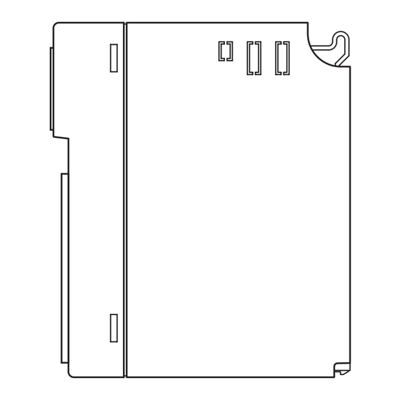
- Page 2 R3Y-SS8 COMPONENT IDENTIFICATION SIDE VIEW FRONT VIEW RUN LED ERR LED • Pin Assignment Range Input Connector Conv. Input 1-4 (SW1) Rate Input 5-8 (SW2) SIDE DIP SW STATUS INDICATOR LED •Input Range: SW1, SW2 (selectable per 4 channels) RUN indicator: Bi-color (red/green) LED;...
- Page 3 M-System's sole liability, and purchaser's exclusive remedies, under this warranty are, at M-System's option, the repair, replacement or refund of the purchase price of any M-System product which is defective under the terms of this warranty. To submit a claim under this warranty, the purchaser must return, at its expense, the defective M-System product to the below address together with a copy of its original sales invoice.
Need help?
Do you have a question about the R3Y-SS8 and is the answer not in the manual?
Questions and answers