Advertisement
INSTRUCTION MANUAL
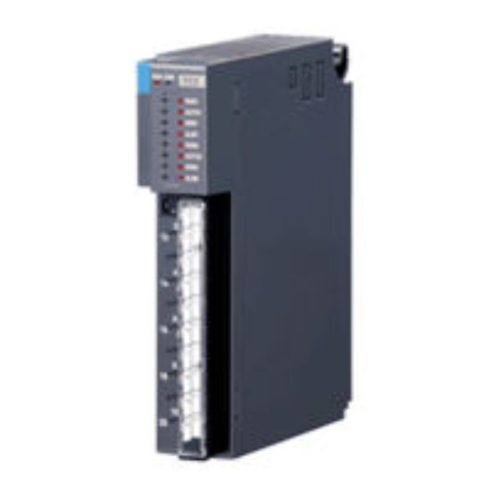
ONE-SHOT PULSE OUTPUT MODULE
(negative common transistor output (NPN), 16 points)
BEFORE USE ....
Thank you for choosing M-System. Before use, please check
contents of the package you received as outlined below.
If you have any problems or questions with the product,
please contact M-System's Sales Office or representatives.
■ PACKAGE INCLUDES:
One-shot pulse output module ..................................... (1)
■ MODEL NO.
Confirm Model No. marking on the product to be exactly
what you ordered.
■ INSTRUCTION MANUAL
This manual describes necessary points of caution when
you use this product, including installation, connection and
basic maintenance procedures.
MODEL
POINTS OF CAUTION
■ HOT INSERTION/REMOVAL OF MODULES
• Removing or replacing modules does not affect other mod-
ules on the same backplane. It is possible to replace them
without removing the power supply. However, replacing
multiple modules at once may greatly change line voltage
levels. We recommend that you replace them one by one.
• In order to prevent the erroneous output at the hot inser-
tion/removal when ON/OFF control output is in one-shot
output mode, the first data received after the hot inser-
tion/removal ia used as initial value. For the combina-
tion with non-cyclic Modbus communication modules (R3-
NM1, R3-NE1, etc.) write the output data immediately
before the hot insertion/removal.
■ CONFORMITY WITH EC DIRECTIVES
• The equipment must be mounted inside the instrument
panel of a metal enclosure.
• The actual installation environments such as panel con-
figurations, connected devices and connected wires may
affect the protection level of this unit when it is integrated
in a panel system. The user may have to review the CE
requirements in regard to the whole system and employ
additional protective measures to ensure CE conformity.
■ ENVIRONMENT
• Indoor use
• When heavy dust or metal particles are present in the air,
install the unit inside proper housing with sufficient ven-
tilation.
• Do not install the unit where it is subjected to continuous
vibration. Do not subject the unit to physical impact.
• Environmental temperature must be within -10 to +55°C
(14 to 131°F) with relative humidity within 30 to 90% RH
in order to ensure adequate life span and operation.
■ WIRING
• Do not install cables (power supply, input and output)
close to noise sources (relay drive cable, high frequency
line, etc.).
• Do not bind these cables together with those in which
noises are present. Do not install them in the same duct.
INSTALLATION
Use the Installation Base (model: R3-BSx).
R3-PD16A
R3-PD16A
EM-8397 Rev.1
P. 1 / 10
Advertisement
Table of Contents

Related Manuals for M-system R3-PD16A


Summary of Contents for M-system R3-PD16A
- Page 1 MODEL (negative common transistor output (NPN), 16 points) BEFORE USE ..POINTS OF CAUTION Thank you for choosing M-System. Before use, please check ■ HOT INSERTION/REMOVAL OF MODULES contents of the package you received as outlined below. • Removing or replacing modules does not affect other mod- If you have any problems or questions with the product, ules on the same backplane.
-
Page 2: Component Identification
R3-PD16A COMPONENT IDENTIFICATION I FRONT VIEW I SIDE VIEW Functions RUN LED ON/OFF Control Output Channel I/O Mode ERR LED Output Status Indicator ON Time Functions Data Length Output Mode Output Hold ■ STATUS INDICATOR LED RUN indicator: Bi-color (red/green) LED; Red when the bus A operates normally; Green when the bus B operates normally;... - Page 3 R3-PD16A • Output ON time: SW1 For setting Output ON time, DIP switch 1 through 8 correspond to each binary digit 1st through 8th digit. For every setting, ON time will be as indicated below. ON TIME (sec.) 25.5 25.6 0.1 (*) SW1-1 SW1-2 SW1-3 SW1-4 SW1-5 SW1-6 SW1-7 SW1-8 EM-8397 Rev.1 P. 3 / 10...
- Page 4 R3-PD16A EXAMPLE OF OPERATION MODES The operation mode can be set with the side DIP switch. Also output hold and output OFF at a continuous output mode can be set. ■ ONE-SHOT OUTPUT MODE (1 through 4 show changes after Do 1 is completed. 5 through 10 changes Do 1 during output state.) Example of I/O Mode is in Output Operation. (SW2-7: OFF) (1) Output data Do 1 changes from 0 to 1. (2) After Do 1’s rising edge, Ch1’s one-shot output turns ON for a fixed period of time (SW1’s time set). (3) After one-shot output completion, Di 1 (Ch1 output completed status) changes from 0 to 1. (4) When Do 1 changes from 1 to 0, Di 1 changes from 1 to 0. (5) Output Data Do 1 changes from 0 to 1 again. (6) After Do 1’s rising edge, Ch1’s one-shot output turns ON for a fixed period of time (SW1’s time set). (7) (8) (9) During one-shot output is ON, Do 1 changes from 0 to 1 to 0. (10) Since Do 1 changes to 0 during one-shot output is 1, Di 1 (Ch1 output completion status) doesn’t change. (5) (7) (8) (9) Do 1 (2) One Shot Output (6) One Shot Output (3) Ch1 One Shot Output Completion...
- Page 5 R3-PD16A Data Length: 8 bits • Example that ON/OFF control outputs sequentially Ch2 to Ch1 is shown below. Example of when I/O Mode is in Output Operation (SW2-7: OFF) and ON/OFF Control channel is Not Swapped (SW2-8: OFF). (1) Output data Do 1 changes from 0 to 1. (2) After Do 1’s rising edge, Ch2’s one-shot output turns ON for a fixed period of time (SW1’s time set). (3) After one-shot output completion, Di 2 (Ch2 output completed status) changes from 0 to 1. (4) When Do 1 changes from 1 to 0, Di 2 changes from 1 to 0. (5) After Do 1’s sinking edge, Ch1’s one-shot output turns ON for a fixed period of time (SW1’s time set). (6) After one-shot output completion, Di 1 (Ch1 output completed status) changes from 0 to 1. Do 1 (5) One Shot Output (2) One Shot Output...
- Page 6 R3-PD16A ■ ONE-SHOT OUTPUT MODE 16-bit output data (Do 1 through 16) and output (Ch1 through 16) are assigned 1:1. When I/O Mode is in Output Operation (SW2-7: ON), Output Complete Status is not indicated. WRITE ONE-SHOT OUTPUT/RESET OUTPUT COMPLETION STATUS Ch1 Output Di 1 Ch1 Output Completion Status Do 1 Ch1 Output Completion Reset Ch2 Output Di 2 Ch2 Output Completion Status...
- Page 7 R3-PD16A ■ ON/OFF CONTROL OUTPUT MODE • Data Length: 16 bits Do 1 through 16 are assigned to Ch1 through 16. When I/O Mode is in Output Operation (SW2-7: ON), Output Complete Status is not indicated. WRITE ONE-SHOT OUTPUT/RESET OUTPUT COMPLETION STATUS 0 0 Not Operating 1 0 Ch1 Output Di 1...
- Page 8 R3-PD16A • Data Length: 8 bits Do 1 through 8 are assigned to Ch1 through 16 as 1:2. One (1) data sets two (2) outputs. When I/O Mode is in Output Operation (SW2-7: ON), Output Complete Status is not indi- cated. WRITE ONE-SHOT OUTPUT/RESET OUTPUT COMPLETION STATUS Ch1 Output Di 1 Ch1 Output Completion Status...
-
Page 9: Data Assignment
R3-PD16A DATA ASSIGNMENT ■ Do Do 1 Do 2 Do 3 Do 16 Note. For 8-bit length ON/OFF control mode, Do 9 through Do 16 are unavailable. ■ Di Di 1 Di 2 Di 3 Di 16 Note. Di data is not practical discrete input data. It is “output completion status” internal data. EM-8397 Rev.1 P. 9 / 10... -
Page 10: Terminal Connections
M-System’s option, the repair, replacement or refund of the purchase price of any M-System product which is defective under the terms of this warranty. To submit a claim under this warranty, the purchaser must return, at its expense, the defective M-System product to the below address together with a copy of its original sales invoice.
Need help?
Do you have a question about the R3-PD16A and is the answer not in the manual?
Questions and answers