Table of Contents
Advertisement
Quick Links
Advertisement
Table of Contents

Related Manuals for thomann Stairville DJ Lase RGB Pro Advanced 1000


Summary of Contents for thomann Stairville DJ Lase RGB Pro Advanced 1000
- Page 1 DJ Lase RGB Pro Advanced 1000 Showlaser...
- Page 2 Thomann GmbH Hans-Thomann-Straße 1 96138 Burgebrach Germany Telephone: +49 (0) 9546 9223-0 Internet: www.thomann.de 20.10.2023, ID: 368582 (V5)
-
Page 3: Table Of Contents
Table of contents Table of contents General information..........................6 1.1 Symbols and signal words....................... 6 Safety instructions............................. 9 Features............................... 16 Installation..............................17 Starting up..............................23 Connections and operating elements................... 25 Operating..............................32 7.1 Switching the device on and off....................32 7.2 Main menu............................ - Page 4 Table of contents Plug and connection assignment....................59 Troubleshooting............................62 Cleaning............................... 64 Protecting the environment......................65 DJ Lase RGB Pro Advanced 1000 Showlaser...
- Page 5 DJ Lase RGB Pro Advanced 1000 Showlaser...
-
Page 6: General Information
Our products and documentation are subject to a process of continuous development. They are therefore subject to change. Please refer to the latest version of the documentation, which is ready for download under www.thomann.de. 1.1 Symbols and signal words In this section you will find an overview of the meaning of symbols and signal words that are used in this document. - Page 7 General information Signal word Meaning DANGER! This combination of symbol and signal word indicates an immediate dangerous situation that will result in death or serious injury if it is not avoided. WARNING! This combination of symbol and signal word indicates a pos‐ sible dangerous situation that can result in death or serious injury if it is not avoided.
- Page 8 General information Warning signs Type of danger Warning – suspended load. Warning – danger zone. DJ Lase RGB Pro Advanced 1000 Showlaser...
-
Page 9: Safety Instructions
Safety instructions Safety instructions Intended use This unit is used to project laser light effects; it is intended for show applications only. Use the device only as described in this user manual. Any other use or use under other operating con‐ ditions is considered to be improper and may result in personal injury or property damage. - Page 10 Safety instructions Safety DANGER! Risk of injury and choking hazard for children! Children can suffocate on packaging material and small parts. Children can injure themselves when handling the device. Never allow children to play with the packaging material and the device. Always store packaging material out of the reach of babies and small children.
- Page 11 Safety instructions DANGER! Risk of injury due to stray laser radiation! Additional components inadequately secured to the device as well as reflective objects and surfaces at the operating location can cause stray laser radiation, which can cause injuries. Make sure that additional components are always secured adequately. Make sure there are no reflective objects or surfaces in the range of the laser beams.
- Page 12 Safety instructions NOTICE! Risk of fire due to covered vents and neighbouring heat sources! If the vents of the device are covered or the device is operated in the immediate vicinity of other heat sources, the device can over‐ heat and burst into flames. Never cover the device or the vents. Do not install the device in the immediate vicinity of other heat sources.
- Page 13 Safety instructions NOTICE! Risk of fire due to incorrect polarity! Incorrectly inserted batteries may cause fires and destroy the device and the batteries. Observe the markings on the batteries and on the device. Ensure that proper polarity is observed when inserting batteries. NOTICE! Possible damage due to leaking batteries! Batteries can leak and cause permanent damage to the device.
- Page 14 Safety instructions Duties of the operator As the operator of the laser system, you must comply with legal occupational safety obliga‐ tions as per the OStrV (in Germany). The following applies in particular: Before putting into service, draw up an assessment of the risk posed by the direct and indi‐ rect effects of laser beams in line with the regulations applicable at the operating location.
- Page 15 Safety instructions Use an additional safety switch (emergency stop switch) installed in an easily accessible central monitoring location (e.g. control room) that switches off the laser immediately and safely in the event of danger. Always remove the key from the key switch when not using the laser, in order to prevent unintentional laser radiation and unauthorised use.
-
Page 16: Features
Features Features Professional RGB laser for use in all event areas: Colour mixing based on analogue diode modulation Laser power: 1000 mW Laser class: 4 Control options: – DMX-512 (20 channels) – ILDA – Infrared remote control (included) – built-in buttons and display –... -
Page 17: Installation
Installation Installation Unpack and check carefully there is no transportation damage before using the unit. Keep the equipment packaging. To fully protect the product against vibration, dust and moisture during transportation or storage use the original packaging or your own packaging material suitable for transport or storage, respectively. - Page 18 Installation DANGER! Risk of injury due to improper installation! If the laser is set up incorrectly and the installation point is too low or too close to persons, there is a significant risk of injury due to the high intensity of the laser beam.
- Page 19 Installation DANGER! Risk of injury due to stray laser radiation! Additional components inadequately secured to the device as well as reflective objects and surfaces at the operating location can cause stray laser radiation, which can cause injuries. Make sure that additional components are always secured adequately. Make sure there are no reflective objects or surfaces in the range of the laser beams.
- Page 20 Installation DANGER! Risk of injury due to inadequate warning signals! Persons unable to assess the dangers of a class 4 laser are at significant risk of injury and irreversible damage if such persons are not informed of the use of the laser.
- Page 21 Installation NOTICE! Risk of overheating and fire due to inadequate distance and bad ventilation! If the distance between the light source and the illuminated surface is too short or the device is badly ventilated, the device can overheat and cause fires. Make sure that illuminated surfaces are more than 2 m away.
- Page 22 Installation Inserting the battery into the Push the lock of the battery holder towards the centre of the housing and pull out the battery remote control holder like a drawer. Insert the batteries. The battery is correct if the positive pole points to the housing base of the remote control.
-
Page 23: Starting Up
Starting up Starting up Create all connections while the device is off. Use the shortest possible high-quality cables for all connections. Take care when running the cables to prevent tripping hazards. NOTICE! Data transfer errors due to improper wiring! If the DMX connections are wired incorrectly, this can cause errors during the data transfer. - Page 24 Starting up Connections in DMX mode Connect the DMX input of the device to the DMX output of a DMX controller or another DMX device. Connect the output of the first DMX device to the input of the second one, and so on to form a daisy chain.
-
Page 25: Connections And Operating Elements
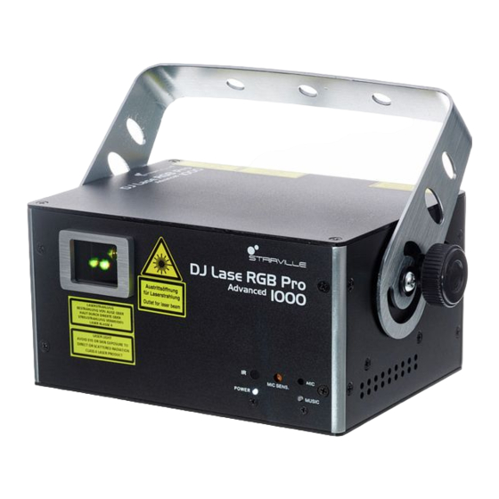
Connections and operating elements Connections and operating elements Front ö DJ Lase RGB Pro I000 Advanced MIC SENS. POWER MUSIC ' & DJ Lase RGB Pro Advanced 1000 Showlaser... - Page 26 Connections and operating elements 1 Laser aperture 2 Retainer and mounting bracket 3 [MIC] | Microphone for sound-controlled operation 4 [MUSIC] | Indicator LED, flashes blue in sound-controlled operation. 5 [Mic Sensitivity] | Rotary control for adjusting the sensitivity of the built-in microphone for sound control 6 [POWER] | Indicator LED, lights up white permanently when the device is on.
- Page 27 Connections and operating elements Back DJ Lase RGB Pro ILDA THROUGH I000 Advanced CONTROL LASER ILDA INPUT DMX-512 POWER DMX OUT DMX IN MENU DOWN ENTER PS 2 INTERLOCK REMOTE LOCK DJ Lase RGB Pro Advanced 1000 Showlaser...
- Page 28 Connections and operating elements 8 Safety cable eyelet 9 [LASER] | Indicator LED, lights up white permanently when the device is on. 10 [POWER] | Indicator LED, lights up red permanently when the laser is on (key switch in the [ON] position) 11 Display 12 [ILDA THROUGH] | 25-pin ILDA output socket for looping through the ILDA signal to other devices 13 [ILDA INPUT] | 25-pin ILDA input socket...
- Page 29 Connections and operating elements 19 Connection for optional remote safety switch (emergency stop). An adapter for safety switches equipped with phone jacks is included in the delivery. 20 [DMX IN] | DMX input [DMX OUT] | DMX output DJ Lase RGB Pro Advanced 1000 Showlaser...
- Page 30 Connections and operating elements IR remote control ö & -/-- DJ Lase RGB Pro Advanced 1000 Showlaser...
- Page 31 Connections and operating elements 1 On / off switch. When the device is in the Auto Show mode or is performing a self test, press the button for several seconds to enter the Remote control mode. When the device is already in the ‘Remote control’ mode, this button switches the laser on or off. 2 No function 3 Stops or restarts a running show.
-
Page 32: Operating
Operating Operating 7.1 Switching the device on and off DANGER! Risk of injury due to improper operation! There is a risk of injury if the device is not operated properly. Only operate the laser after approval has been granted, and under the supervi‐ sion of a laser protection representative. - Page 33 Operating Switching on Perform the following steps to switch the device on: Verify that all required laser safety precautions have been taken. Make sure that there is no one in the reach of the laser beam. Connect an external safety switch (e.g. emergency stop switch) or an equivalent system with a protection function to the [REMOTE] connection.
-
Page 34: Main Menu
Operating 7.2 Main menu Press [MENU] to open the main menu. Press [MENU] repeatedly or press [UP] and [DOWN] to select one of the following menu items: AUTO, MUSIC, TEXT, TIME, COUNTDOWN, DMX, SLAVE or SYSTEM. Press [ENTER] to open the selected menu. -
Page 35: System Menu
Operating 7.3 SYSTEM menu In this menu, you can adjust various device settings. Press [MENU] to open the main menu. Press [MENU] repeatedly or press [UP] and [DOWN] to select the ‘SYS’ menu and confirm with [ENTER]. Parameter Meaning Value range ‘Nirr’... -
Page 36: Operating Modes
Operating 7.4 Operating modes Operating mode AUTO In this mode, the device automatically projects programmed patterns in the selected mode onto a surface. Press [MENU] to open the main menu. Press [MENU] repeatedly or press [UP] and [DOWN] to select the ‘Aut’ menu item and confirm with [ENTER]. - Page 37 Operating Parameter Meaning ‘Aut 7’ Auto mode 7, show with programmed Party motto patterns. ‘Aut 8’ Auto mode 8, show with programmed Halloween motto patterns. ‘Aut 9’ Auto mode 9, show with programmed Music motto patterns. DJ Lase RGB Pro Advanced 1000 Showlaser...
- Page 38 Operating SOUND mode In this mode, the device projects programmed patterns sound-controlled onto a surface. Set the sensitivity of the built-in microphone using the [Mic Sensitivity] adjustment screw on the front of the housing. Press [MENU] to open the main menu. Press [MENU] repeatedly or press [UP] and [DOWN] to select the ‘Sou’...
- Page 39 Operating Parameter Meaning ‘Sou 8’ Sound mode 8, show with programmed Halloween motto patterns. ‘Sou 9’ Sound mode 9, show with programmed Music motto patterns. TEXT mode In this mode, the device projects text that has been entered and saved via the supplied key‐ board (see ) onto a surface.
- Page 40 Operating TIME mode In this mode, the device consecutively projects time, date and the day of the week onto a sur‐ face. Press [MENU] to open the main menu. Press [MENU] repeatedly or press [UP] and [DOWN] to select the ‘tiM’ menu item and confirm with [ENTER].
- Page 41 Operating Operating mode COUNTDOWN In this mode, the device projects a linked text ( ‘t-01’ … ‘t-09’ ) onto a surface after a pro‐ grammed countdown time. Press [MENU] to open the main menu. Press [MENU] repeatedly or press [UP] and [DOWN] to select the ‘Cnt’ menu item and confirm with [ENTER].
-
Page 42: Setting Dmx Channel
Operating The display shows ‘d001’ , the device is now controlled via DMX channel 1. When the display flashes, no controller is connected. To return to the main menu without making changes, press [MENU]. 7.5 Setting DMX channel Switch to the DMX mode. The display shows ‘d001’ . Press [ENTER]. - Page 43 Operating Channe Value Function 50 … 99 Sound mode 100 … 149 Text mode 150 … 199 Selecting the first pattern 200 … 255 Selecting the second pattern Auto mode, channel 1 = 10 … 79 0 … 29 AUTO1 30 …...
- Page 44 Operating Channe Value Function 0 … 29 MUSIC1 30 … 59 MUSIC2 60 … 89 MUSIC3 90 … 119 MUSIC4 120 … 149 MUSIC5 150 … 179 MUSIC6 180 … 209 MUSIC7 210 … 239 MUSIC8 240 … 255 MUSIC9 Pattern mode, channel 1 = 151 …...
- Page 45 Operating Channe Value Function 160 … 191 Pattern group 6 192 … 223 Pattern group 7 224 … 255 Pattern group 8 Pattern selection, channel 1 = 151 … 255, channel 2 = 0 … 255 0 … 255 Patterns 1 to 16 of the respectively selected group of channel 2 (16 patterns x 8 groups = 128 patterns) Colour selection 0 …...
- Page 46 Operating Channe Value Function 64 … 111 Single colour conversion 112 … 159 Multi-coloured motion above and below, increasing speed 160 … 207 Multi-coloured motion left to right, increasing speed 208 … 255 Strobe effect, increasing speed Drawing of pattern (clipping) Original pattern, no Clipping effect 1 …...
- Page 47 Operating Channe Value Function Y axis rotation 0 … 127 Fixed adjusted position of Y-axis 128 … 191 Y-axis rotation clockwise 192 … 255 Y-axis rotation counter-clockwise Rotation speed of Y-axis 0 … 255 Rotation speed of Y-axis from slow to fast X axis rotation 0 …...
- Page 48 Operating Channe Value Function 192 … 255 Z-axis rotation counter-clockwise Rotation speed of Z-axis 0 … 255 Rotation speed of Z-axis from slow to fast X-axis mouving 0 … 127 Fixed adjusted position of X-axis 128 … 191 Rotation around X-axis clockwise 192 …...
-
Page 49: Operating Via Keyboard
Operating Channe Value Function Wave effect 0 … 255 Increasing wave size Wave effect 0 … 255 Increasing wave frequency Wave effect 0 … 127 Wave position 128 … 255 Wave motion speed from slow to fast 7.7 Operating via keyboard The functions of the device can also be controlled via the supplied keyboard. - Page 50 Operating General functions Button Symbol Function Windows® Start button, opens the main menu (). Use the arrow keys and to switch between the menu options. Confirm to open a subordinate menu and to activate a selection with [Enter]. Functions in AUTO mode Button Symbol Function...
- Page 51 Operating Functions in SOUND mode Button Symbol Function [Pause] Stops the running program in the motion of the currently projected pattern. Press the button again to let the programme continue. [RGB | Manual change between the fixed colours red, green, yellow, blue, Color] pink and white during the current projection.
- Page 52 Operating Button Symbol Function [Zoom] Activates the Zoom function: the entered text is zoomed out, disap‐ pears and is zoomed out again. The zoom speed can be adjusted with the arrow buttons and . Press the button again to deactivate the function.
- Page 53 Operating Button Symbol Function [Z Roll] Activates the rolling motion in the Z-axis: the entered text performs a clockwise circular motion on the projection surface. The motion speed can be adjusted with the arrow buttons and . Press the button repeatedly to reverse the direction of the circular motion or to disable the function.
- Page 54 Operating Button Symbol Function [Loop Loop key. This button is used to start an endless loop playback of playback] the text saved under ‘t-01’ … ‘t-09’ . [PgUP] Browse key. Activates the previous program location where text is saved. [PgDN] Browse key.
-
Page 55: Menu Overview
Operating 7.8 Menu overview Aut1 Sou1 t-00 tINe Coun d001 SLAU Nirr rSEt Aut9 Sou9 t-09 d492 irEn tEHt N-En Si2e N-PP N-nP N-Pn 7.9 Reset to factory defaults To reset the device to factory default settings, open the SYSTEM menu (see ), select the menu item ‘rSET’... -
Page 56: Technical Specifications
Technical specifications Technical specifications Laser medium Red: 638 nm (typical), LD Green: 532 nm (typical), LD Blue: 450 nm (typical), LD Laser power Red: 200 mW Green: 200 mW Blue: 600 mW Laser class Beam diameter at aperture < 5 mm Divergence (each beam) <... - Page 57 Technical specifications Output connections DMX control XLR chassis socket, 3-pin Number of DMX channels Control DMX, infrared remote control, ILDA, buttons and display on the device, USB keyboard Supply voltage 100 - 240 V 50/60 Hz Power consumption 25 W Fuse 5 mm ×...
- Page 58 Technical specifications Further information Colour spectrum Animation laser Grating laser Analogue modulation DJ Lase RGB Pro Advanced 1000 Showlaser...
-
Page 59: Plug And Connection Assignment
Plug and connection assignment Plug and connection assignment Introduction This chapter will help you select the right cables and plugs to connect your valuable equip‐ ment so that a perfect light experience is guaranteed. Please take our tips, because especially in ‘Sound & Light’ caution is indicated: Even if a plug fits into a socket, the result of an incorrect connection may be a destroyed DMX controller, a short circuit or ‘just’... - Page 60 Plug and connection assignment Intensity+ Locking (Interlock) A User-defined signal 1+ User-defined signal 2+ User-defined signal 3+ User-defined signal 4+ Return signal from the unit Shutter X– Y– Intensity– Locking (Interlock) B DJ Lase RGB Pro Advanced 1000 Showlaser...
- Page 61 Plug and connection assignment R– G– B– User-defined signal 1– User-defined signal 2– User-defined signal 3– User-defined signal 4– Ground DJ Lase RGB Pro Advanced 1000 Showlaser...
-
Page 62: Troubleshooting
Troubleshooting Troubleshooting DANGER! Risk of injury due to improper troubleshooting! There is a risk of injury if troubleshooting is not performed properly. Have all work and repairs on class 4 lasers performed by trained experts. In the following we list a few common problems that may occur during operation. We give you some suggestions for easy troubleshooting: DJ Lase RGB Pro Advanced 1000 Showlaser... - Page 63 When the unit receives a signal from the remote control the LED ‘MUSIC’ lights up briefly. 3. Check the remote control battery. If the procedures recommended above do not succeed, please contact our Service Center. You can find the contact information at www.thomann.de. DJ Lase RGB Pro Advanced 1000 Showlaser...
-
Page 64: Cleaning
Cleaning Cleaning DANGER! Risk of injury due to improper cleaning! There is a risk of injury if cleaning is not performed properly. To avoid unintentional laser radiation, always remove the key from the key switch before you start cleaning the device. Optical lenses Clean the optical lenses, that are accessible from the outside, regularly in order to optimize the light output. -
Page 65: Protecting The Environment
Protecting the environment Protecting the environment Disposal of the packaging mate‐ rial For the packaging, environmentally friendly materials have been chosen that can be supplied to normal recycling. Ensure that plastic bags, packaging, etc. are properly disposed of. Do not just dispose of these materials with your normal household waste, but make sure that they are collected for recycling. - Page 66 Protecting the environment Disposal of your old device This product is subject to the European Waste Electrical and Electronic Equipment Directive (WEEE) in its currently valid version. Do not dispose with your normal household waste. Dispose of this device through an approved waste disposal firm or through your local waste facility.
- Page 68 Musikhaus Thomann · Hans-Thomann-Straße 1 · 96138 Burgebrach · Germany · www.thomann.de...
Need help?
Do you have a question about the Stairville DJ Lase RGB Pro Advanced 1000 and is the answer not in the manual?
Questions and answers