
Subscribe to Our Youtube Channel
Related Manuals for Contacta STS-K001L


Summary of Contents for Contacta STS-K001L
- Page 1 Window Intercom System Bridge Bar Kit - STS-K001L Installation & User Guide January 2020...
-
Page 2: Table Of Contents
Contents Product Overview Components Connections Installation Instructions Speaker & Microphone Kit Installation Staff Side Installation Customer/Visitor Side Installation Hearing Loop Installation Amplifier Setup Troubleshooting Engineers Mode Contacta has a policy of continuous product development, and therefore small specification changes may not be reflected in this manual. Images, labels, packaging, accessories and product colours are subject to change without notice. -
Page 3: Product Overview
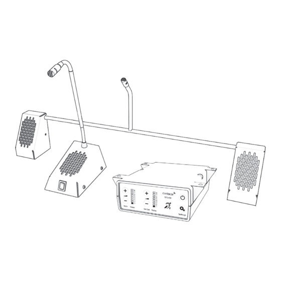
Product Overview Window intercom systems provide assistance for clear communication where normal speech is impaired by use of glass, a security screen or other similar barriers. There is a hearing loop facility included, providing additional assistance for hearing device wearers. Speaker & Microphone Components 1. Staff Microphone 2. Bridge Bar General Components... -
Page 4: Connections
Connections Hearing Loop Bridge Bar Power Supply Staff Microphone Power input connection Use power supply through ground supply only Staff microphone Hearing loop aerial Customer/visitor speaker Customer/visitor microphone Confidence LED (if required) for status alerts Staff speaker and fault detection Line in connection for LED connection or alert tone (if required) external audio source Confidence LED to confirm the system is powered or an alert tone for the attention of staff... -
Page 5: Installation Instructions
Installation Instructions We recommend that installation is carried out by a qualified engineer, adhering to relevant standards. Check the contents of the box to familiarise yourself with the components. Recommended Tools A toolkit recommended to install the system will include: • Screwdrivers (Flat or Blade 2.5mm • Pliers and Phillips Head PH2) • Tape Measure • Battery or Mains Drill • Pencil or Marker Pen • Drillbits: 2mm, 3mm, 5mm and 7mm •... -
Page 6: Speaker & Microphone Kit Installation
Speaker & Microphone Kit Installation Staff Side Installation Fixing points 1. Place the staff microphone on the staff side of the counter top, ensuring that it does not cause an obstruction and is as close to staff as possible. 2. Place the amplifier under the staff counter, ensuring that it will not obstruct staff when they are sitting. 3. Mark the four fixing points for the amplifier under the counter. 4. Drill and fix the amplifier in place using the supplied screws. 5. Use a cable management hole to run the staff microphone cable back to the amplifier. If there is not already a cable management hole, drill in a suitable location near the rear of the surface. 6. Install the amplifier’s power supply close to a power socket outlet using the supplied mounting bracket and fixing screws. -
Page 7: Customer/Visitor Side Installation
Customer/Visitor Side Installation 1. Place the bridge bar on the counter top in a central location over the pass-through tray. 2. Disassemble the speaker pods by undoing the screws and removing the housing. Allen grub Housing screws fixing points Allen grub screws 3. If the bridge bar needs to be narrowed, calculate the width required (minimum: 450mm) with the following steps: a. Locate the allen grub screws on the mounting bracket and loosen... - Page 8 Cable holes Fixing points 6. Ensure there will be access to retrieve the cables, then drill the holes. 7. Fix the speaker pods to the counter and feed the wiring through the cable management holes. 8. Refit the housing using the screws previously removed. 9. Avoid loose or trailing cables. Use trunking or to prevent trip hazards or units being tugged from their position. 10. Route all the cabling neatly to the amplifier location on the staff side.
-
Page 9: Hearing Loop Installation
Hearing Loop Installation The aerial should be fixed under the desk-top or counter centrally on the custome or visitor side, one half mounted horizontally under the counter and the other half mounted vertically, facing the customer/visitor (as in the first scenario below). Position the aerial under the counter using either the provided P-clips or another fixing method of your choice. See the diagram below for recommended positioning. A is the optimum layout for a counter hearing loop. B and C are acceptable only if A is not possible and the layout is aligned so that the magnetic field will be directed towards user’s head heights. Ensure all hearing loop signage is displayed clearly. -
Page 10: Amplifier Setup
Amplifier Setup Overview of Front Panel Buttons On/Off Settings Volume In (Customer/Visitor to Staff) Volume Out (Staff to Customer/Visitor) Increase and decrease Increase and decrease Setup 1. Connect all green plugs to the back of the amplifier, following the locations printed above the sockets (see page 4). 2. Power on the amplifier by pressing the On/Off button. 3. When powered and in normal operational mode the amplifier will display Volume In LED 1 and Volume Out LED 1 as steady green. 4. When the amplifier is switched off, all audio is muted and none of the LEDs are illuminated. Pressing any button will turn the amplifier on again. 5. Adjust Volume In and Volume Out to a comfortable level. 6. Press and hold the Volume In (+) or (-) buttons to increase or decrease the level. The corresponding LED bar will show the volume setting. - Page 11 Fault Diagnosis LEDs • Volume In LED 8 will stay red if there is a fault with the staff microphone. • Volume Out LED 8 will stay red if there is a fault with the customer/visitor microphone. • Volume In LED 8 will flash red if there is a fault with the loop (e.g. a broken aerial). Factory Default Settings To return the amplifier to the factory default settings: 1. Unplug the power supply and then reconnect it. 2. The LED indicators will show a light pattern in the “Vol In” column. This indicates the firmware revision. This will be followed by a green light at the bottom of each column.
-
Page 12: Troubleshooting
2) Microphone positioned too close 2) Move the microphone to a to speaker. location further from the speaker. 1) Ambient noise in area is too high. 1) Switch off any air con systems, Unit does not desktop fans and/or computers to go into power reduce ambient noise. saving mode. If no action is successful please seek assistance from your distributor or a Contacta installer. -
Page 13: Engineers Mode
Engineer’s Mode Engineers Mode allows you to adjust the Volume In and Out levels, Ducking levels and Hearing Loop levels to better suit your environment and achieve the best possible performance. Before entering Engineer’s Mode, cycle the power. To do this either: • Switch the power off at the mains socket and back on again • Remove the power connector and re-insert it To enter Engineer’s Mode, simultaneously press and release the following buttons within 20 seconds of cycling the power: •... - Page 14 1. Ensure the customer/visitor and staff volumes are turned down. 2. Adjust staff (Volume In) volume to a comfortable level. Press and hold the Volume In (+) or (-) buttons to increase or decrease the level. The corresponding LED bar will show the volume setting. 3. Raise customer/visitor (Volume Out) volume until feedback is heard. Press and hold the Volume Out (+) or (-) buttons to increase or decrease the level. The corresponding LED bar will show the volume setting. 4. Lower customer/visitor (Volume Out) volume until feedback is eliminated. Setup Area 2: Ducking Adjustment (LED 2 flashes) Setup Area 2 allows you to adjust the Ducking level or to turn it on/off. The ducking function is provided to reduce feedback on a window intercom system. Feedback occurs when the overall setting of both volume controls is too high. The ducking system works by detecting which microphone in the conversation is being used, and temporarily reducing the volume setting.
- Page 15 there are peaks in the speech volume. If the amplifier does not have a loop attached, turn the Hearing Loop Drive off as indicated in the diagram above.
- Page 16 Further information is available on our website and our YouTube channel. Window Intercom STS-A31H Amplifier Window Intercom Unboxing & Setup Video Positioning Guide Video www.contacta.co.uk sales@contacta.co.uk +44 (0) 1732 223900 Technical Support - Ext 5...
Need help?
Do you have a question about the STS-K001L and is the answer not in the manual?
Questions and answers