Table of Contents
Advertisement
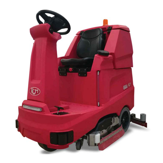
GIGA
ITA
EN
NL
FR
5/2020 Rev.01
MANUALE D'USO E MANUTENZIONE
INSTRUCTION AND MAINTENANCE HANDBOOK
HANDLEIDING VOOR GEBRUIK EN ONDERHOUD
MANUEL D'UTILISATION ET D'ENTRETIEN
via Tiraboschi, 4 - 41043 Casinalbo - Modena - Italia
Tel. +39 059 515 311 - Fax +39 059 510 783
www.rcm.it - info@rcm.it
33.GI.101 - GIGA 702R
33.GI.102 - GIGA 802
33.GI.103 - GIGA 902
RCM S.p.A.
Advertisement
Table of Contents

Related Manuals for RCm GIGA 702R


Summary of Contents for RCm GIGA 702R
- Page 1 GIGA 33.GI.101 - GIGA 702R 33.GI.102 - GIGA 802 33.GI.103 - GIGA 902 MANUALE D’USO E MANUTENZIONE INSTRUCTION AND MAINTENANCE HANDBOOK HANDLEIDING VOOR GEBRUIK EN ONDERHOUD MANUEL D’UTILISATION ET D’ENTRETIEN 5/2020 Rev.01 RCM S.p.A. via Tiraboschi, 4 - 41043 Casinalbo - Modena - Italia Tel.
-
Page 2: Table Of Contents
CONTENTS INDICE Page Pagina INFORMAZIONI PRELIMINARI PRELIMINARY INFORMATION GENERALITÀ GENERAL INFORMATION ► Dati per l’identifi cazione della Macchina ► Identifi cation data of the machine RICHIESTE DI INTERVENTO REQUESTS FOR ASSISTANCE RICAMBI SPARE PARTS NORME DI SICUREZZA GENERALI GENERAL SAFETY STANDARDS NORME DA SEGUIRE DURANTE IL FUNZIONAMENTO STANDARDS TO FOLLOW DURING OPERATION NORME PER LA MANUTENZIONE... - Page 3 INHOUDSOPGAVE SOMMAIRE Pagina Page INFORMATIE VOORAF INFORMATIONS PRÉLIMINAIRES ALGEMEEN GÉNÉRALITÉS ► Gegevens voor de identifi catie van de machine ► Données d’identifi cation de la machine INTERVENTIEAANVRAGEN DEMANDES D’INTERVENTION RESERVEONDERDELEN PIÈCES DE RECHANGE ALGEMENE VEILIGHEIDSNORMEN CONSIGNES GÉNÉRALES DE SÉCURITÉ NORMEN DIE TIJDENS DE WERKING GEVOLGD MOETEN WORDEN RÈGLES À...
-
Page 4: Informazioni Preliminari
INFORMAZIONI PRELIMINARI PRELIMINARY INFORMATION I seguenti simboli hanno la funzione di attirare l’attenzione del lettore/utilizza- The following symbols are intended to attract the reader/user's attention so that tore ai fi ni di un uso corretto e sicuro della macchina, più precisamente hanno il the machine is used properly and safely, more precisely they mean the following: seguente signifi cato: Attention! - Page 5 INFORMATIE VOORAF INFORMATIONS PRÉLIMINAIRES De volgende symbolen zijn bedoeld om de aandacht van de lezer/gebruiker te La fonction des symboles suivants consiste à attirer l'attention du lecteur/utilisa- trekken teneinde de machine correct en veilig te gebruiken. Meer bepaald heb- teur, pour un usage correct et en toute sécurité de la machine, pour la précision ben ze de volgende betekenis: ils ont la signifi cation suivante : Opgepast!
-
Page 6: Generalità
GENERALITÀ {FIG.1} GENERAL INFORMATION {FIG.1} Identifi cation data of the machine Dati per l’identifi cazione della Macchina Targhetta riassuntiva del tipo di macchina Summary plate of the machine type ALGEMEEN {AFB.1} GÉNÉRALITÉS {FIG.1} Gegevens voor de identifi catie van de machine Données d'identifi cation de la machine Plaatje met overzicht van het type machine Plaque récapitulative du type de machine... -
Page 7: Norme Di Sicurezza Generali
NORME DI SICUREZZA GENERALI GENERAL SAFETY STANDARDS La macchina descritta nel presente manuale è stata costruita in confor- The machine described in this manual is manufactured in compliance mità alla Direttiva Comunitaria sulle macchine 2006/42/CE (Direttiva Macchine). with the EU Directive 2006/42/EC (Machinery Directive). It is the obligation of È... - Page 8 ALGEMENE VEILIGHEIDSNORMEN CONSIGNES GÉNÉRALES DE SÉCURITÉ De machine beschreven in deze handleiding werd gebouwd in overeen- La machine décrite dans ce manuel a été fabriquée conformément à la stemming met de communautaire richtlijn betreff ende machines 2006/42/EG Directive Communautaire sur les machines 2006/42/CE (Directive Machines). Le (Machinerichtlijn).
-
Page 9: Norme Da Seguire Durante Il Funzionamento
NORME DA SEGUIRE DURANTE STANDARDS TO FOLLOW IL FUNZIONAMENTO DURING OPERATION Non lasciare avvicinare alla macchina persone estranee al lavoro. Do not let persons who are not involved in the work approach the machine. L’uso della macchina é consentito solo agli operatori autorizzati dal responsa- The machine must only be used by operators authorised by the person responsi- bile della gestione della macchina e a conoscenza del contenuto del presente ble for machine management and who is familiar with the contents of this man-... - Page 10 NORMEN DIE TIJDENS DE WERKING RÈGLES À SUIVRE GEVOLGD MOETEN WORDEN PENDANT LE FONCTIONNEMENT Ne pas laisser des personnes étrangères s'approcher de la machine. Laat geen onbevoegde personen de machine naderen. Alleen bedieners die hiervoor toestemming kregen van de verantwoordelijke L’utilisation de la machine n’est consentie qu’aux opérateurs autorisés par le responsable de la gestion de la machine et qui connaît le contenu du présent voor het beheer van de machine, die de inhoud van deze handleiding perfect...
-
Page 11: Movimentazione Macchina Imballata
MOVIMENTAZIONE PACKAGED MACCHINA IMBALLATA MACHINE HANDLING La macchina giunge imballata su pallet. The machine comes packed on a pallet. Il peso e le dimensioni sono riportate nelle CARATTERISTICHE TECNICHE. The weight and dimensions are given in the TECHNICAL DATA. Le forche del carrello o del transpallet devono essere posizionate in modo che The forks of the truck or manual pallet truck must be positioned so that the cen- il centro dell’imballo sia circa al centro delle forche stesse. - Page 12 MANUTENTION VERPLAATSING DE LA MACHINE EMBALLÉE VAN DE VERPAKTE MACHINE La machine arrive emballée sur une palette. De machine wordt verpakt op een pallet geleverd. Le poids et les dimensions sont mentionnés dans les CARACTÉRISTIQUES TECH- Het gewicht en de afmetingen staan vermeld in de TECHNISCHE KENMERKEN. NIQUES.
-
Page 13: Caratteristiche Tecniche
CARATTERISTICHE TECNICHE {1/3} Versioni GIGA 702 R GIGA 802 GIGA 902 Prestazioni Massima capacità oraria di lavaggio 5250 m²/h 6000 m²/h 6750 m²/h Larghezza di lavaggio 700 mm 800 mm 900 mm Larghezza di asciugatura 965 mm 965 mm 965 mm Velocità... - Page 14 CARATTERISTICHE TECNICHE {2/3} Versioni GIGA 702 R GIGA 802 GIGA 902 Motori elettrici Motore trazione n.1 - 24V - 750W n.1 - 24V - 750W n.1 - 24V - 750W Motore rotazione spazzole n.2 - 24V - 500W n.2 - 24V - 500W n.2 - 24V - 500W Motore aspirazione n.1 - 36V - 600W...
- Page 15 CARATTERISTICHE TECNICHE {3/3} Versioni GIGA 702 R GIGA 802 GIGA 902 Peso macchina Peso a vuoto senza operatore, senza batteria 259 Kg 258 Kg 268 Kg Peso a vuoto senza operatore, con n.4 batterie 6V - 180Ah 395 Kg 398 Kg 406 Kg Peso a vuoto senza operatore, con n.4 batterie 6V - 205Ah 385 Kg...
-
Page 16: Technical Features
TECHNICAL FEATURES {1/3} Versions GIGA 702 R GIGA 802 GIGA 902 Performance Maximum hourly washing capacity 5250 m²/h 6000 m²/h 6750 m²/h Cleaning width 700 mm 800 mm 900 mm Drying width 965 mm 965 mm 965 mm Max. travel speed 8 Km/h 8 Km/h 8 Km/h... - Page 17 TECHNICAL FEATURES {2/3} Versions GIGA 702 R GIGA 802 GIGA 902 Electric motors Drive motor No. 1 - 24V - 750W No. 1 - 24V - 750W No. 1 - 24V - 750W Brush rotation motor No. 2 - 24V - 500W No.
- Page 18 TECHNICAL FEATURES {3/3} Versions GIGA 702 R GIGA 802 GIGA 902 Machine weight Weight when empty, without operator, without battery 259 Kg 258 Kg 268 Kg Weight when empty without operator, with 4 batteries 6V - 180Ah 395 Kg 398 Kg 406 Kg Weight when empty without operator, with 4 batteries 6V - 205Ah 385 Kg...
- Page 19 TECHNISCHE KENMERKEN {1/3} Versies GIGA 702 R GIGA 802 GIGA 902 Prestaties Maximaal wasvermogen per uur 5250 m²/u 6000 m²/u 6750 m²/u Wasbreedte 700 mm 800 mm 900 mm Droogbreedte 965 mm 965 mm 965 mm Max. rijsnelheid vooruit 8 km/u 8 km/u 8 km/u Max.
- Page 20 TECHNISCHE KENMERKEN {2/3} Versies GIGA 702 R GIGA 802 GIGA 902 Elektrische motoren Tractiemotor n.1 - 24V - 750W n.1 - 24V - 750W n.1 - 24V - 750W Motor voor rotatie van de borstels n.2 - 24V - 500W n.2 - 24V - 500W n.2 - 24V - 500W Aanzuigmotor...
- Page 21 TECHNISCHE KENMERKEN {3/3} Versies GIGA 702 R GIGA 802 GIGA 902 Gewicht van de machine Leeg gewicht zonder bediener, zonder batterij 259 kg 258 kg 268 kg Leeg gewicht zonder bediener, met 4 batterijen 6 V - 180 Ah 395 kg 398 kg 406 kg Leeg gewicht zonder bediener, met 4 batterijen 6 V - 205 Ah...
- Page 22 CARACTÉRISTIQUES TECHNIQUES {1/3} Versions GIGA 702 R GIGA 802 GIGA 902 Performances Capacité horaire maximale de lavage 5250 m²/h 6000 m²/h 6750 m²/h Largeur de lavage 700 mm 800 mm 900 mm Largeur de séchage 965 mm 965 mm 965 mm Vitesse maxi de déplacement 8 Km/h 8 Km/h...
- Page 23 CARACTÉRISTIQUES TECHNIQUES {2/3} Versions GIGA 702 R GIGA 802 GIGA 902 Moteurs électriques Moteur de traction 1 à 24V - 750W 1 à 24V - 750W 1 à 24V - 750W Moteur de rotation des brosses 2 à 24V - 500W 2 à...
- Page 24 CARACTÉRISTIQUES TECHNIQUES {3/3} Versions GIGA 702 R GIGA 802 GIGA 902 Poids de la machine Poids à vide sans opérateur, sans batterie 259 Kg 258 Kg 268 Kg Poids à vide sans opérateur, avec 4 batteries 6V - 180Ah 395 Kg 398 Kg 406 Kg Poids à...
-
Page 25: Comandi E Componenti
COMANDI E COMPONENTI {FIG.3} CONTROLS AND COMPONENTS {FIG.3} COMMANDO'S EN COMPONENTEN {AFB.3} COMMANDES ET COMPOSANTS {FIG.3} Volante / Cruscotto comandi Sedile con micro di sicurezza Lampada a LED - LED lamp LED-lamp - Lampe LED Steering wheel / Control dashboard Seat with safety micro Stoel met veiligheidsmicro Stuur / instrumentenbord met commando’s... -
Page 26: Descrizione Comandi E Componenti
3a. Videata: 1a. Scherm: Successivamente alle informazioni sopra descritte il display visualizzerà la Logo RCM / Naam en model van de machine schermata di lavoro ed eventuali allarmi e i seguenti simboli. 2a. Scherm: Urenteller (gedeeltelijk en volledig) 3. - Page 27 4. Pulsante comando avvisatore acustico Comanda l’avvisatore acustico. 4. Horn command button This controls the horn. 4. Knop voor bediening van de akoestische waarschuwing Stuurt de akoestische waarschuwing aan. 4. Bouton de commande du klaxon Il commande le klaxon. 5. Pulsante spazzole/elettrovalvola e pompa acqua Comanda l’attivazione, l’abbassamento e rotazione spazzole, l’eltrovalvola e la pompa acqua con livelli impostabili da 1 a 5.
- Page 28 10. Pulsante regolazione pressione delle spazzole Premendo sul pulsante si regola la pressione delle spazzole sul pavimento con livelli impostabili da 1 a 3. La regolazione verrà indicata sul display. 10. Brush pressure adjustment button Press the button to adjust the pressure of the brushes on the fl oor with levels settable from 1 to 3.
- Page 29 14. Pulsante modalità “MY-GIGA” Questa funzione permette di stabilire e fi ssare i parametri di funzionamento rela- tivi alla quantità d’acqua, detergente (solo con Detersaver) e pressione spazzole (Vedere capitolo MODALITÀ DI LAVORO MY-GIGA”). La funzione verrà indicata sul display. (*) = All’accensione della macchina mediante la chiave, queste regolazio- ni si posizionano sui valori impostati precedentemente.
- Page 30 17. Serbatoio recupero (acqua sporca) Contiene l’acqua sporca che dalle spazzole di lavaggio viene aspirata dal tergi- pavimento. Al termine di ogni lavaggio scaricare l’acqua sporca dal serbatoio e pulirlo (vedere “SCARICO ACQUA E PULIZIA DEL SERBATOIO DI RECUPERO”). 17. Recovery tank (dirty water) Contains the dirty water which, from the washing brushes, is vacuumed up by the squeegee.
- Page 31 22. Sedile con microinterruttore di sicurezza Sedile di guida con microinterruttore di sicurezza situato sotto al sedile nella zona “B”. Il microinterruttore non permette nessuna funzione della macchina se l’operatore non è seduto sul sedile stesso. Attenzione! Se l’operatore non è correttamente seduto sul sedile 22 e preme sul pe- dale acceleratore 21, la macchina non si muove, il display mostrerà...
- Page 32 27. Faro di lavoro Si attiva automaticamente all’accensione della macchina. 27. Work light This is activated automatically when the machine is switched on. 27. Werkschijnwerper Deze wordt automatisch geactiveerd wanneer de machine wordt ingeschakeld. 27. Phare de travail Il s’active automatiquement à l’allumage de la machine. 28.
-
Page 33: Uso Della Lavasciuga
USO DELLA LAVASCIUGA USING THE SCRUBBER Precauzioni necessarie Necessary precautions • La lavasciuga deve essere usata solo da personale autorizzato compe- • The scrubber must only be used by competent and skilled authorised tente e responsabile. personnel. • Quando si lascia la lavasciuga incustodita, occorre togliere la chiave •... - Page 34 UTILISATION GEBRUIK VAN DE DE LA LAVEUSE-SÉCHEUSE VLOERREINIGINGSMACHINE Précautions nécessaires Nodige voorzorgsmaatregelen • La laveuse-sécheuse ne doit être utilisée que par un personnel autorisé • De vloerreinigingsmachine mag alleen door bekwaam en verantwoor- compétent et responsable. delijk personeel worden gebruikt dat hiervoor toestemming werd ver- •...
-
Page 35: Carico Acqua E Fase Di Lavaggio
CARICO ACQUA E WATER LOADING AND FASE DI LAVAGGIO {FIG.5} WASHING PHASE {FIG.5} Carico acqua Water loading Prima di ogni lavaggio, riempire il serbatoio soluzione 1 con la giusta quantità di Before each wash, fi ll solution tank 1 with the right amount of water* (*Maximum acqua* (*Temperatura massima acqua 50°C ) e detergente aprendo il tappo 2. - Page 36 WATER VULLEN CHARGEMENT DE L’EAU EN WASFASE {AFB.5} ET PHASE DE LAVAGE {FIG.5} Water vullen Chargement de l’eau Vóór iedere wasbeurt moet u de tank voor de oplossing 1 vullen met de juiste Avant chaque lavage, remplir le réservoir de solution 1 avec la bonne quanti- hoeveelheid water* (*Maximumtemperatuur van het water 50 °C) en schoon- té...
-
Page 37: Modalita Di Lavoro "Standard
MODALITA DI LAVORO “STANDARD” “STANDARD” {FIG.6} OPERATING MODE {FIG.6} Accensione della macchina Switching on the machine All’accensione del sistema elettrico mediante chiave di avviamento 23 {fi g.4}) su When the electrical system is switched on with the ignition key 23 {fi g.4}) in pos.1, pos.1 , compare il logo, successivamente sul display vengono visualizzate il tipo the logo appears, then the display shows the machine type, the software version, di macchina, la versione software, il tipo di batteria ed i contaore, quindi compare... - Page 38 “STANDAARD” MODE DE TRAVAIL WERKWIJZE {AFB.6} « STANDARD » {FIG.6} Inschakeling van de machine Allumage de la machine Wanneer het elektrische systeem wordt ingeschakeld door de contactsleutel 23 À l'allumage du système électrique à l'aide de la clé de contact 23 {fi g.4} sur la {afb.4} op pos.1 te zetten, verschijnt het logo.
-
Page 39: Modalita Di Lavoro "Go Green
MODALITA DI LAVORO “GO GREEN” “GO GREEN” {FIG.7} OPERATING MODE {FIG.7} Questa modalità permette di ridurre i consumi d’acqua, detergente ed energia. To activate the “GO GREEN” mode, simply press . The operator will immedi- ately be able to carry out the washing phase without making adjustments to Per attivare la modalità... -
Page 40: Modalita Di Lavoro "My Giga
MODALITA DI LAVORO “MY GIGA” “MY GIGA” {FIG.8} OPERATING MODE {FIG.8} Con questa questa modalità è possibile stabilire e fi ssare i parametri di funziona- With this mode, you can establish and set the operating parameters relating to mento relativi alla quantità d’acqua, detergente (solo con funzione “Detersaver” the amount of water, detergent (only with the “Detersaver”... - Page 41 “MY GIGA” MODE DE TRAVAIL WERKWIJZE {AFB.8} « MY GIGA » {FIG.8} Via deze werkwijze kun u de werkingsparameters met betrekking tot de hoeveel- Ce mode permet de défi nir et de fi xer les paramètres de fonctionnement relatifs heid water, schoonmaakproduct (alleen met optionele functie “Detersaver”) en à...
-
Page 42: Accessory And Parameter Management | Dealer Level (Enabled)
GESTIONE ACCESSORI E PARAMETRI ACCESSORY AND PARAMETER MANAGEMENT LIVELLO DEALERS (ABILITATI) {FIG.9 - 1/2} DEALER LEVEL (ENABLED) {FIG.9 - 1/2} Nelle Tabelle seguenti vengono visualizzate le impostazioni principali, per acce- The following Tables show the main settings, to access and change the settings, dere e modifi care le impostazioni, premere contemporaneamente i pulsanti “1”... -
Page 43: Gestione Accessori E Parametri | Livello Dealers (Abilitati)
GESTIONE ACCESSORI E PARAMETRI ACCESSORY AND PARAMETER MANAGEMENT LIVELLO DEALERS (ABILITATI) {FIG.9- 2/2} DEALER LEVEL (ENABLED) {FIG.9- 2/2} Impostazioni principali Main settings default default 1. Model selection (seleziona il tipo di macchina) 1. Model selection (selects the type of machine) 702R 702R NB: da settare in caso di modelli diversi da 802 {default}... - Page 44 GESTION DES ACCESSOIRES ET PARAMÈTRES BEHEER VAN ACCESSOIRES EN PARAMETERS NIVEAU REVENDEURS (HABILITÉS) {FIG.9- 2/2} NIVEAU (ERKENDE) DEALERS {AFB.9- 2/2} Belangrijkste instellingen default Confi gurations principales défaut 1. Model selection (selecteert het type machine) 1. Model selection (sélectionner le type de machine) 702R 702R NB: in te stellen in geval van andere modellen dan 802 {default...
-
Page 45: Percentuale Di Scarica Della Batteria E Soglia Di Allerta
PERCENTUALE DI SCARICA DELLA BATTERY DISCHARGE PERCENTAGE BATTERIA E SOGLIA DI ALLERTA AND ALARM THRESHOLDS La centralina elettronica converte il valore della tensione delle batterie in valore The electronic control unit converts the battery voltage value into a percentage percentuale e prevede due soglie di allerta al raggiungimento della scarica della value and provides two alarm thresholds when the battery is discharged at 20% batteria pari al 20% e 10% della capacità. -
Page 46: Scarico Acqua E Pulizia Del Serbatoio Di Recupero
SCARICO ACQUA E PULIZIA DEL WATER DRAINING AND CLEANING THE SERBATOIO DI RECUPERO {FIG.10} RECOVERY TANK {FIG.10} Al termine di ogni lavaggio o quando il serbatoio di recupero 1 è pieno, scaricare At the end of each wash or when recovery tank 1 is full, drain the dirty water l’acqua sporca tramite il tubo di scarico 2. -
Page 47: Scarico Acqua Dal Serbatoio Soluzione E Pulizia Filtro Acqua
WATER DRAINING FROM SCARICO ACQUA THE SOLUTION TANK AND DAL SERBATOIO SOLUZIONE WATER FILTER CLEANING {FIG.11} E PULIZIA FILTRO ACQUA {FIG.11} Solution tank water draining (clean water) Scarico acqua dal serbatoio soluzione (acqua pulita) Remove cap 2 to drain the water from solution tank 1. It is recommended to drain Per scaricare l’acqua dal serbatoio soluzione 1 rimuovere il tappo 2. -
Page 48: Manutenzione
MANUTENZIONE {FIG.12 - 1/4} MAINTENANCE {FIG.12 - 1/4} Attenzione! Attention! Tutte le operazioni di manutenzione devono essere eff ettuate SOLO All maintenance operations must be carried out ONLY by the operator or dall’operatore o dal personale autorizzato e qualifi cato. Prima di proce- authorised and qualifi ed personnel. - Page 49 ONDERHOUD {AFB.12 - 1/4} ENTRETIEN {FIG.12 - 1/4} Opgepast! Attention ! Alle onderhoudswerken mogen ALLEEN door de bediener of door bevoegd, ge- Toutes les opérations d’entretien NE doivent être eff ectuées QUE par kwalifi ceerd personeel worden uitgevoerd. Voordat u verdergaat, en om in veilige l’opérateur ou le personnel autorisé...
-
Page 50: Spazzole "Lavanti" A Rulli
MANUTENZIONE {FIG.12 - 2/4} MAINTENANCE {FIG.12 - 2/4} Attenzione! Attention! Prima di eseguire la manutenzione delle spazzole “lavanti” a rullo, veri- Before carrying out the maintenance of the “washing” roller brush- fi care che non vi siano avvolti corde, fi li di ferro o altri oggetti, ecc., fra i es, check that there are no cords, wires or other objects, etc., wrapped mozzi di trascinamento 6 e le spazzole 4 around them, between the drive hubs 6 and the brushes 4... - Page 51 ENTRETIEN {FIG.12 - 2/4} ONDERHOUD {AFB.12 - 2/4} Attention ! Opgepast! Avant d’eff ectuer l’entretien des brosses « lavantes » à rouleau, vérifi er Voordat onderhoud op de “wassende” rollenborstels uitgevoerd wordt, moet qu’il n’y ait pas de cordes, de fi ls de fer ou d’autres objets, etc. enroulés u controleren of er geen touwen, stukken ijzerdraad of andere voorwerpen entre les moyeux d’entraînement 6 et les brosses 4 tussen de aandrijfnaven 6 en de borstels 4 zitten...
-
Page 52: Tergipavimento
MANUTENZIONE {FIG.12 - 3/4} MAINTENANCE {FIG.12 - 3/4} Attenzione! Attention! Per esigenze d’imballaggio il tergipavimento potrebbe venir fornito For packaging requirements, the squeegee may be supplied disassem- smontato dalla macchina e dovrà essere applicato alla piastra di suppor- bled from the machine and must be applied to the support plate on the to sulla lavasciuga. - Page 53 ENTRETIEN {FIG.12 - 3/4} ONDERHOUD {AFB.12 - 3/4} Attention ! Opgepast! Pour des besoins d’emballage, il se peut que la raclette soit fournie dé- Omwille van de verpakking kan het voorvallen dat de vloerzwabber ge- montée de la machine et qu’il faille l’appliquer à la plaque de support de demonteerd van de machine geleverd wordt.
-
Page 54: Pulizia Del Tergipavimento
MANUTENZIONE {FIG.12 - 4/4} MAINTENANCE {FIG.12 - 4/4} Pulizia del tergipavimento Cleaning the squeegee Smontare il tergipavimento seguendo in modo inverso le istruzioni riportate alla Remove the squeegee by following the instructions in the “MAINTENANCE sezione “MANUTENZIONE {FIG.12 - 3/4}.Smontare le gomme del tergipavimento {FIG.12 - 3/4}”... -
Page 55: Motore Aspirazione
MOTORE ASPIRAZIONE {FIG.13} VACUUM MOTOR {FIG.13} Il motore aspirazione 1 serve ad aspirare l’acqua raccolta dal tergipavimento, me- The vacuum motor 1 is used to vacuum up the water collected by the squeegee, diante l’azionamento del pulsante 6 {fi g. 4}. Lo stesso motore deve essere control- by pressing the button 6 {fi g. -
Page 56: Sistema Avanzamento
SISTEMA AVANZAMENTO {FIG.14} DRIVE SYSTEM {FIG.14} La lavasciuga è mossa da un sistema elettrico composto da un diff erenziale con The scrubber is moved by an electrical system composed of a diff erential with motore elettrico 1 ed elettrofreno posto sulle ruote posteriori e da una centralina electric motor 1 and electric brake placed on the rear wheels and an electronic elettronica 2 che controlla il sistema di avanzamento (vedere capitolo “IMPIANTO control unit 2 which controls the drive system (see chapter “ELECTRICAL SYSTEM... - Page 57 STERZO {FIG.15} STEERING {FIG.15} Lo sterzo é azionato da una catena 1, che trasmette il moto al piantone 2 e alla Steering is operated by chain 1, which transmits motion to column 2 and to corona 3 sulla ruota anteriore. crown 3 on the front wheel.
-
Page 58: Frenatura
FRENATURA {FIG.16} BRAKING {FIG.16} Il sistema di frenatura della lavapavimenti serve per frenare la macchina in movi- The scrubber braking system is used to brake the moving machine and keep it mento e tenerla ferma su superfi ci inclinate. steady on inclined surfaces. La macchina dispone di un freno di servizio elettrico 1 che agisce sul sistema di The machine has an electric service brake 1 that acts on the rear drive system trazione posteriore quando la macchina è... - Page 59 REMSYSTEEM {AFB.16} FREINAGE {FIG.16} Het remsysteem van de vloerreinigingsmachine dient om de rijdende machine af Le système de freinage de l’autolaveuse sert à freiner la machine en mouvement te remmen en op hellende oppervlakken geblokkeerd te houden. et à la laisser immobile sur une surface inclinée. De machine beschikt over een elektrische dienstrem 1 die op het tractiesysteem La machine dispose d’un frein électrique de service 1 qui agit sur le système de achteraan werkt wanneer de machine in beweging is.
-
Page 60: Impianto Elettrico
Gel battery or vice-versa, it is necessary to change the battery type parameter tipo di batteria come descritto alla “FIG.9”. QUESTA OPERAZIONE DEVE ESSERE as described in “FIG.9”. THIS OPERATION MUST ONLY BE CARRIED OUT BY “RCM” ESEGUITA SOLAMENTE DA“RCM” O DA UN DIALER “ABILITATO”. - Page 61 « FIG.9 ». CETTE OPÉRATION king tot het type batterij, zoals beschreven wordt in “AFB.9”. DEZE HANDELING MAG NE DOIT ÊTRE EFFECTUÉE QUE PAR « RCM » OU PAR UN REVENDEUR « AGRÉÉ ». ALLEEN DOOR “RCM” OF DOOR EEN “ERKENDE” DEALER WORDEN UITGEVOERD.
-
Page 62: Caricabatterie A Bordo (Optional)
IMPIANTO ELETTRICO {FIG.17 - 2/6} ELECTRICAL SYSTEM {FIG.17 - 2/6} Caricabatterie a bordo (Optional) On-board battery charger (Optional) Attenzione! Attention! Quando il caricabatterie è connesso alla rete, tutte le funzioni della macchi- When the battery charger is connected to the mains, all machine func- na vengono automaticamente escluse. - Page 63 INSTALLATION ÉLECTRIQUE {FIG.17 - 2/6} ELEKTRISCH SYSTEEM {AFB.17 - 2/6} Ingebouwde batterijlader (optie) Chargeur de batterie à bord (option) Opgepast! Attention ! Wanneer de batterijlader op het net is aangesloten, worden alle functies Quand le chargeur de batteries est connecté au réseau, toutes les fonc- van de machine automatisch uitgesloten.
-
Page 64: Confi Gurazione "Dipswitch" Sul Caricabatterie A Bordo (Optional)
IMPIANTO ELETTRICO {FIG.17 - 3/6} ELECTRICAL SYSTEM {FIG.17 - 3/6} Confi gurazione “DIPSWITCH” sul caricabatterie a bordo per la “DIPSWITCH” confi guration on the on-board battery charger ricarica delle batteria al Piombo Acido o Gel (Optional) to charge Lead-acid or Gel batteries (Optional) Il caricabatterie a bordo CBHD3 è... -
Page 65: Ricarica Delle Batterie Con Caricabatterie Esterno "Optional
Ricarica delle batterie con caricabatterie esterno “optional” Charging the batteries with “optional” external battery charger Per ricaricare le batterie da stazione fi ssa usare un caricabatteria esterno con usci- To charge batteries from fi xed station, use an external battery charger with 24V ta 24V - max 25Ah e collegamento alla rete di tensione e frequenza compatibile output - max 25Ah and connection to the voltage mains and frequency compati- con il paese in cui si utilizza la macchina. -
Page 66: Diagnostica Allarmi
IMPIANTO ELETTRICO {FIG.17 - 4/6} Diagnostica allarmi In caso di anomalia/e o malfunzionamento della macchina, la centralina 8 {Fig.17 - 1/6} visualizzerà l’allarme sul display come da esempio indicato nell’immagine seguente: ELENCO ALLARMI CENTRALINA (ITALSEA 7CFX1050) ► ► Allarme Causa Descrizione AL_1: GENERALE ►... - Page 67 AL_64: FUNZIONE ► Timeout attuatore 2 ► Solo con fi necorsa esterni, se l’attuatore non arriva in posizione fi nale entro un tempo prestabilito (disabilitato per questa macchina). Da verifi care connessioni, condizioni elettriche e meccaniche dell’attuatore. Se non si rilevano cause esterne, può indicare stadio di pilotaggio attuatore guasto.
-
Page 68: Alarms Diagnostics
ELECTRICAL SYSTEM {FIG.17 - 4/6} Alarms diagnostics In case of machine anomalies or malfunctions, the control unit 8 {Fig.17 - 1/6} will show the alarm on the display as per the example indicated in the following image: CONTROL UNIT ALARM DIAGNOSTICS LIST (ITALSEA 7CFX1050) ►... - Page 69 AL_64: FUNCTION ► Timeout actuator 2 ► Only with external limit switches, if the actuator doesn’t reach the fi nal position within a preset time (disabled for this ma- chine). Check the connections, electrical and mechanical conditions of the actuator. If no external causes are detected, this may indicate a faulty actuator pilot stage. AL_65: FUNCTION ►...
- Page 70 ELEKTRISCH SYSTEEM {AFB.17 - 4/6} Diagnostiek alarmen In geval van storing(en) of slechte werking van de machine, geeft de centrale 8 {afb.17 - 1/6} op het display het alarm weer, zoals bijvoorbeeld aangegeven wordt in de volgende afbeelding: LIJST ALARMEN VAN DE BESTURINGSEENHEID (ITALSEA 7CFX1050) ►...
- Page 71 AL_64: FUNCTIE ► Time-out actuator 2 ► Alleen met externe eindloopschakelaars, als de actuator niet binnen een vooraf ingestelde tijd (uitgeschakeld voor deze machine) in de eindpositie komt. Controleer de aansluitingen en de elektrische en mechanische toestand van de actuator. Als er geen externe oorzaken worden gedetecteerd, kan dit duiden op een foutieve testfase van de actuator.
- Page 72 INSTALLATION ÉLECTRIQUE {FIG.17 - 4/6} Diagnostic des alarmes En cas d’anomalie et/ou de dysfonctionnement de la machine, l’unité de contrôle 8 {Fig.17 - 1/6} affi che l’alarme à l’écran comme d’après l’exemple indiqué sur l’image suivante : LISTE DES ALARMES DE L’UNITÉ DE CONTRÔLE (ITALSEA 7CFX1050) ►...
- Page 73 AL_64 : FONCTION ► Timeout actionneur 2 ► Uniquement avec fi ns de course extérieurs, si l’actionneur n’arrive pas dans sa position fi nale dans le délai prédéfi ni (désactivée pour cette machine). Connexions, conditions électriques et mécaniques de l’actionneur à vérifi er. Si aucune cause externe n’est constatée, cela peut indi- quer que l’étage pilote de l’actionneur est défectueux.
-
Page 74: Schema Elettrico
IMPIANTO ELETTRICO ELECTRICAL SYSTEM SCHEMA ELETTRICO {FIG.17 - 5/6} WIRING DIAGRAM {FIG.17 - 5/6} ELEKTRISCH SYSTEEM INSTALLATION ÉLECTRIQUE ELEKTRISCH SCHEMA {AFB.17 - 5/6} SCHÉMA ÉLECTRIQUE {FIG.17 - 5/6}... -
Page 75: Wiring Diagram
IMPIANTO ELETTRICO ELECTRICAL SYSTEM SCHEMA ELETTRICO {FIG.17 - 6/6} WIRING DIAGRAM {FIG.17 - 6/6} INSTALLATION ÉLECTRIQUE ELEKTRISCH SYSTEEM SCHÉMA ÉLECTRIQUE {FIG.17 - 6/6} ELEKTRISCH SCHEMA {AFB.17 - 6/6} R 16.00 M2 R 16.00 M2 Legenda colori cablaggio Wiring colors: {A - Azzurro} {B - Bianco} {C - Arancio} {G - Giallo} {H - Grigio} {L - Blu} {A - Light Blue} {B - White} {C - Orange} {G - Yellow} {H - Grey} {L - Blue} {M - Marrone} {N - Nero} {R - Rosso} {S - Rosa} {V - Verde} {Z - Viola} {M - Brown} {N - Black} {R - Red} {S - Pink} {V - Green} {Z - Violet}... -
Page 76: Operazioni Periodiche Di Controllo E Manutenzione
OPERAZIONI PERIODICHE PERIODIC CONTROL, DI CONTROLLO E MANUTENZIONE MAINTENANCE E CONTROLLI DI SICUREZZA AND SAFETY CHECKS La macchina deve essere ispezionata da un tecnico specializzato che controlli le The machine must be inspected by a qualifi ed technician who checks its safety condizioni di sicurezza della stessa o la presenza di eventuali danni o difetti nei conditions or for any damage or defects in the following cases: seguenti casi:... - Page 77 PERIODIEKE HANDELINGEN VOOR OPÉRATIONS PÉRIODIQUES DE CONTROLE EN ONDERHOUD EN CONTRÔLE ET D’ENTRETIEN ET VEILIGHEIDSCONTROLES CONTRÔLES DE SÉCURITÉ De machine moet door een gespecialiseerde technicus gecontroleerd worden, La machine doit être inspectée par un technicien spécialisé qui contrôle les con- die de veilige condities van de machine controleert en nagaat of er geen schade ditions de sécurité...
-
Page 78: Ricerca Dei Guasti
RICERCA DEI GUASTI {1/2} Difetto Causa Rimedio Il tergipavimento non asciuga Gomme tergipavimento usurate Sostituire le gomme Tergipavimento intasato Pulire il tergipavimento Un corpo estraneo si è incastrato nel tergipavimento Rimuovere il corpo estraneo Tubo aspirazione intasato Pulire il tubo Tergipavimento regolato male Regolare l’inclinazione (vedere “MANUTENZIONE {FIG.12 - 3/4}) Tappo del tubo di scarico acqua aperto... - Page 79 RICERCA DEI GUASTI {2/2} Difetto Causa Rimedio La macchina non procede nè in avanzamento nè in Connettore pedale acceleratore scollegato Ricollegare connettore retromarcia. Microinterruttore di sicurezza sotto al sedile, rotto Sostituire microinterruttore Diff erenziale con motore elettrico di trazione dan- Sostituire motore o carboncini neggiato o carboncini usurati.
-
Page 80: Troubleshooting
TROUBLESHOOTING {1/2} Problem Cause Solution The squeegee does not dry Worn squeegee rubber blades Replace the rubber blades Squeegee clogged Clean the squeegee A foreign object has become wedged in the Remove the foreign object squeegee Vacuum hose clogged Clean the hose Squeegee poorly adjusted Adjust the tilt angle (see “MAINTENANCE {FIG.12 - 3/4}) Water drain hose cap open... - Page 81 TROUBLESHOOTING {2/2} Problem Cause Solution The machine does not move forward or in reverse. Accelerator pedal connector disconnected Reconnect connector Safety micro-switch under the seat, broken Replace micro-switch Diff erential with electric traction motor damaged or Replace motor or carbon brushes carbon brushes worn.
- Page 82 DEFECTEN OPSPOREN {1/2} Defect Oorzaak Oplossing De vloerzwabber droogt niet Rubbers van de vloerzwabber versleten Vervang de rubbers Vloerzwabber verstopt Reinig de vloerzwabber Er zit een vreemd voorwerp vast in de vloerzwabber Verwijder het vreemde voorwerp Aanzuigslang verstopt Reinig de leiding Vloerzwabber niet goed afgesteld Regel de inclinatie (zie “ONDERHOUD {AFB.12 - 3/4}) Dop van de leiding om water af te laten staat open...
- Page 83 DEFECTEN OPSPOREN {2/2} Defect Oorzaak Oplossing De machine rijdt niet vooruit en ook niet achteruit. Connector versnellingspedaal losgekoppeld Sluit de connector opnieuw aan Veiligheidsmicroschakelaar onder de stoel is stuk Vervang de microschakelaar Diff erentiaal met elektrische tractiemotor bescha- Vervang de motor of de kooltjes digd of kooltjes versleten.
- Page 84 DÉPANNAGE {1/2} Défaut Cause Solution La raclette ne sèche pas Lames en caoutchouc de raclette usées Remplacer les lames Raclette obstruée Nettoyer la raclette Un corps étranger s'est encastré dans la raclette Enlever le corps étranger Tuyau d'aspiration obstrué Nettoyer le tuyau Raclette mal réglée Régler l’inclinaison (cf.
- Page 85 DÉPANNAGE {2/2} Défaut Cause Solution La machine ne bouge pas, ni en marche avant ni en Connecteur de pédale de l’accélérateur, débranché Rebrancher le connecteur marche arrière. Micro-interrupteur de sécurité sous le siège, cassé Remplacer le micro interrupteur Diff érentiel avec moteur électrique de traction en- Remplacer le moteur ou les balais de charbon dommagé...
-
Page 86: Informazioni Di Sicurezza
INFORMAZIONI DI SICUREZZA SAFETY INFORMATION Pulizia Cleaning Nelle operazioni di pulizia e di lavaggio della macchina i detergenti aggressivi, In the cleaning and washing operations of the machine, aggressive detergents, acidi, ecc., devono essere usati con cautela. Attenersi alle istruzioni del produt- acids, etc., must be used with caution.
Need help?
Do you have a question about the GIGA 702R and is the answer not in the manual?
Questions and answers